2 installing the rack, Installation and wiring 60 – Toshiba T2N User Manual
Page 75
4.Installation and Wiring
60
PROSEC T2N
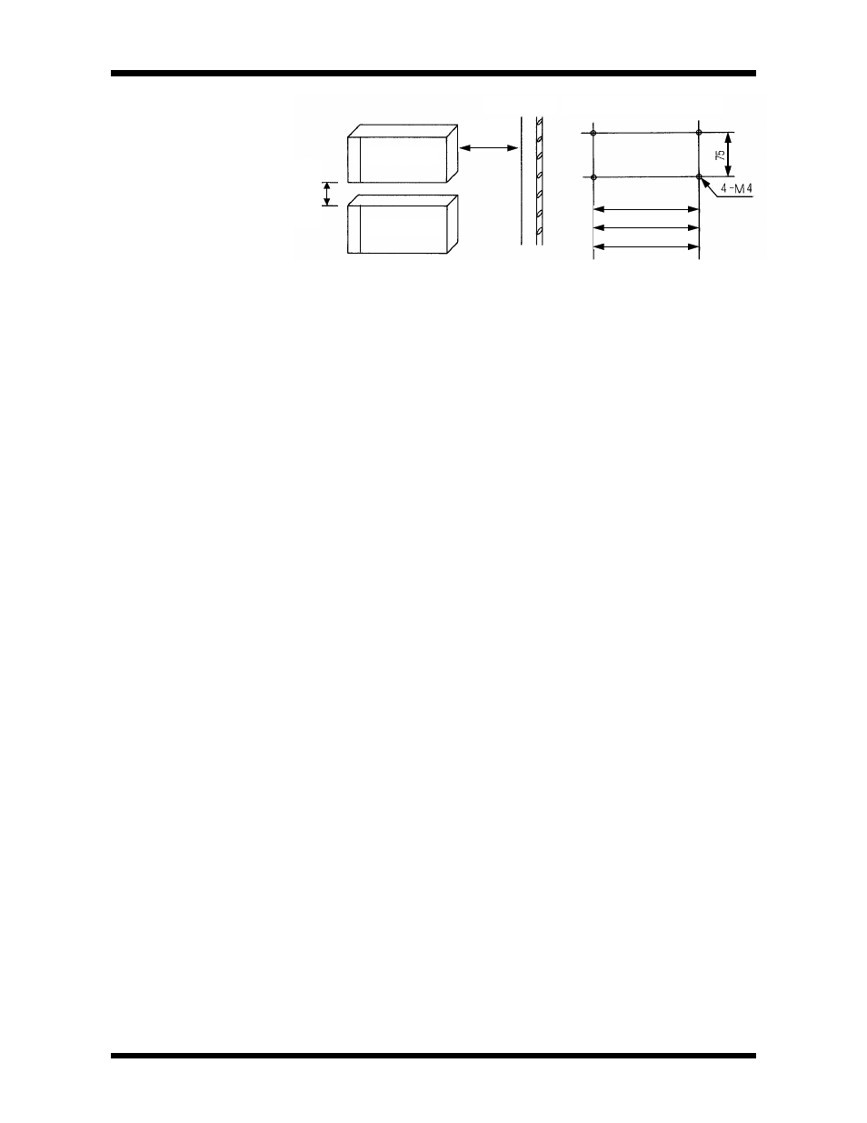
200mm
or more
70mm
or more
Power line
Installation dimensions
Expansion unit
Basic unit
248(BU266)
314(BU266)
380(BU228N)
Installation Precautions
(1) Since the T2N is not of dust-proof construction, install it in a dust-proof
control panel.
(2) Avoid installing the units directly above equipment which generates large
amounts of heat (such as heaters, transformers and large capacity
resistors).
(3) Taking account of safety in maintenance and operation, either isolate at
least 200mm from high-voltage equipment and power equipment, or
separate by shielding, such as steel plate.
(4) Separate at least 200mm from high-voltage lines and high power lines.
(5) For ventilation, leave an air space of at least 70mm around the units.
(6) In paticular, in the vicinity of high-voltage and power equipment, it is
necessary to give consideration to grounding.(See 4.5 Grounding)
(7) In the units, the power supply modules are always positioned on the left-
hand side. Install them vertically on the mounting frame.
Do not install them in the direction except it.
(8) Mount the units securely, using the rack mounting screws of M4 size.
(Screws torque : approx.1.47N
⋅
m=15kgf
⋅
cm)
4.2
Installing the Rack