Application precautions for i/o modules – Toshiba T2N User Manual
Page 70
3.Application Precautions for I/O Modules
User’s manual 55
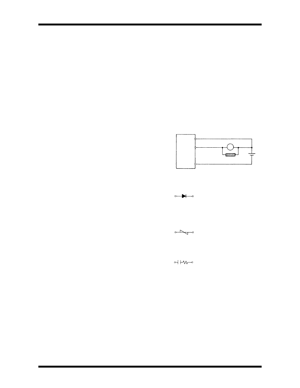
(5) If a capacitive load is connected, rush current will flow when
output is charged to ON.
At that time, necessary measures must be taken to protect the output
transistor from being destroyed by the rush current.
To limit the rush current there are two effective measures. One is to
connect a resistor to the load in series. The other is to apply dummy current
to the load by conncting a resistor between the output terminals.
(6) If an inductive load is connected, transient overvoltage will occur when the
output is changed to OFF.
This surge voltage will be absorbed into the diode D mentioned
before so that the transistor will be protected. However,if the output cable
is installed closely to other signal lines, the surge voltage may cause other
problem. In this case, install a flywheel diode in parallel with the inductive
load (as near as possible to the load).
A suitable surge absorption element should be selected according to the
application.
•Flywheel diode
Peak inverse voltage:
(for voltage clamping)
3 times the power supply
voltage or more
Forward current:
Load current or more
‚Varistor
Rated voltage about
(for voltage clamping)
twice the maximum(peak)
power supply voltage.
ƒSnubber(CR)
R:0.5 - 1
Ω
per 1V coil
voltage circuit(for high
voltage
frequency attenuation)
C:0.5 - 1
µ
F per 1A coil
current
(Non-polar capacitor)
Transistor
Output
module
L