Texas Instruments TMS320C64x DSP User Manual
Page 181
Display T
iming
Examples
4-36
V
ideo Display Port
SPRU629
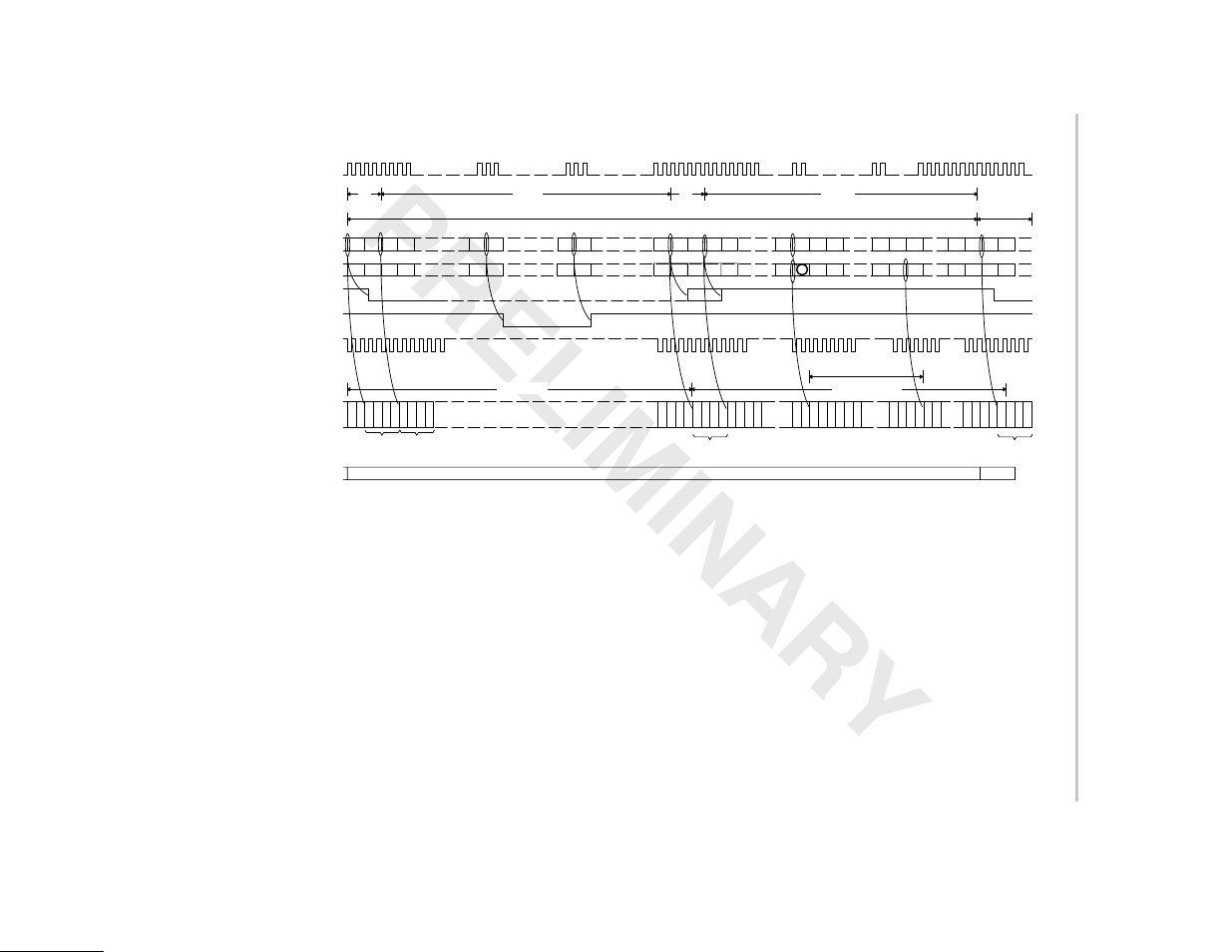
Figure 4–33. BT.656 Interlaced Display Horizontal Timing Example
720 721 722 723
735 736
799 800
855 856
857 0
1
7
8
9
10
710 711 712
718 719 720 721
703 703 703 703
703 703
703 703
703 703 703
703
0
1
2
702 703
703
703
703
703 703
n + 1
n
FLCOUNT
VCLKOUT
VCTL1 (HBLNK)† §
IPCOUNT
FPCOUNT
VCLKIN
VCTL1 (HSYNC)† §
VDOUT[9–0]
n – 1
4
268
4
1440
One Line
Next Line
‡
Blanking
Active Video
Display Image
EAV Blanking Data
SAV
EAV
703
703
Def
Cr
Def
Y
FF
.C
00.
0
00.
0
XY
.0
80.
0
10.
0
10.
0
80.
0
80.
0
10.
0
10.
0
80.
0
FF
.C
00.
0
00.
0
XY
.0
Def
Cb
Def
Y
Def
Cr
Def
Y
Def
Cr
Def
Y
Cb0
Y0
Cr
0
Y1 Cb1
Y2
Cb351
Y702 Cr351
Y703 Def
Cb
Def
Y
Def
Cb
Def
Y
Def
Cr
Def
Y
FF
.C
00.
0
00.
0
XY
.0
FRMWIDTH = 858
IMGHOFF1 = 8
HSYNCSTART = 736
HBLNKSTART = 720
IMGHSIZE1 = 704
HSYNCSTOP = 800
HBLNKSTOP = 856
IMGHOFF2 = 8
IMGHSIZE2 = 704
† Assumes VCT1P bit in VPCTL is set to 1 (active-low output). HSYNC output when VCTL1S bit in VDCTL is set to 00,
HBLNK output when VCTL1S bit is set 01.
‡ HBLNK operation when HBDLA bit in VDHBLNK is set to 1.
§ Diagram assumes a two VCLK pipeline delay between internal counters and output signals.