Texas Instruments TMS320C64x DSP User Manual
Page 101
TSI Capture Mode
3-39
Video Capture Port
SPRU629
Figure 3–23. Program Clock Reference (PCR) Header Format
47
15
14
9
8
0
PCR
Reserved
PCR extension
The video port, in conjunction with the VCXO interpolated control (VIC), allows
a combined hardware and software solution to synchronize the local system
time clock (STC) with the encoder time clock reference transmitted in the bit
stream.
The video port maintains a hardware counter that counts the system time. The
counter is driven by a system time clock (STCLK) input driven by an external
VCXO. The counter is split into two fields: a 33-bit field (PCR base) that counts
at 90 kHz and a 9-bit field (PCR extension) that counts at 27 MHz. The 9-bit
counter counts from 0 to 299 at 27 MHz. Each time the 9-bit counter rolls over
to 0, the 33-bit counter is incremented by 1. This is equivalent to the PCR time-
stamp transmitted in the bit-stream. The 33-bit field can also be programmed
to count at 27 MHz for compatibility with the MPEG-1 32-bit PCR, by setting
the CTMODE bit in VCCTL to 1; in which case, the PCR extension portion of
the counter is not used. Figure 3–24 shows the system time clock counter
operation.
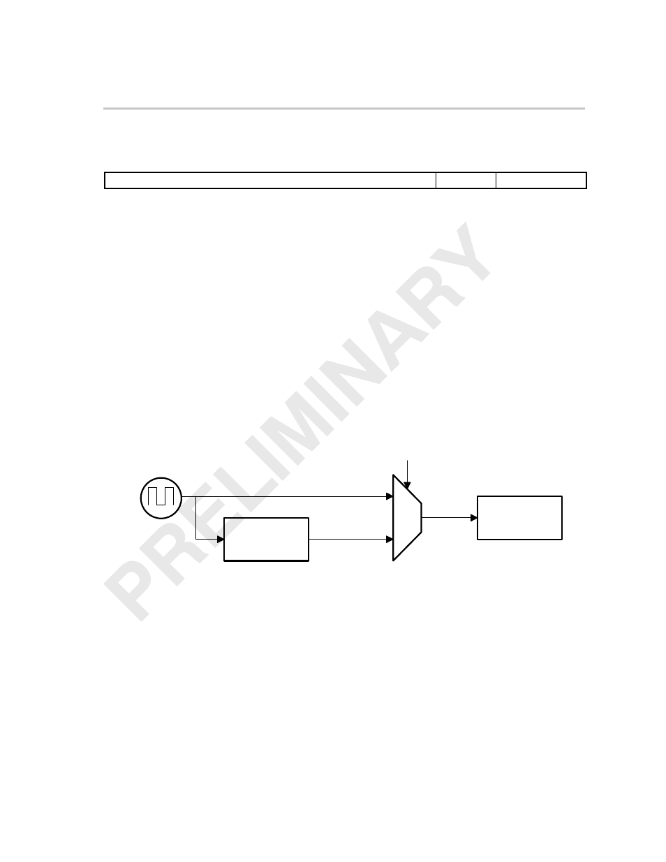
Figure 3–24. System Time Clock Counter Operation
27 MHz
Modulo 300
Counter 233
PCR Extension
PCR Base
CTMODE
0
1
STCLK
90 kHz
External VCXO
On reception of a packet (during the sync byte), a snapshot of the counter is
captured. This snapshot, or timestamp, is inserted in the receiving FIFO at the
end of each data packet. Software uses this timestamp, to determine the devi-
ation of the local system time clock from the encoder time clock. Any time a
packet with a PCR header is received, the timestamp for that packet is
compared with the PCR value by software. A PLL is implemented in software
to synchronize the STCLK with the encoder time clock value in the PCR. This
algorithm then drives the VIC, which drives the VDAC output to the external
VCXO, which supplies STCLK.