4 edge pixel replication, Figure 4–20. 2x co-sited scaling, Figure 4–21. 2x interspersed scaling – Texas Instruments TMS320C64x DSP User Manual
Page 168: Figure 4–22. output edge pixel replication
Video Output Filtering
4-23
Video Display Port
SPRU629
Figure 4–20. 2x Co-Sited Scaling
2
×
upscaled output
YCbCr 4:2:2 co–sited
source pixels
Luma (Y)
sample
Y’d’ = (–1Yc + 17Yd + 17Ye – 1Yf ) / 32
Cb’d = (–1Cba + 17Cbc + 17Cbe – 1Cbg ) / 32
Cr’d = (–1Cra + 17Crc + 17Cre – 1Crg ) / 32
–
Chroma (Cb/Cr)
samples
–
a
a’
b
b’
c
c’
d
d’
e
e’
f
f’
a
b
c
d
e
f
g
g
Cr’c = Crc
Cb’c = Cbc
Y’b = Yb
Figure 4–21. 2x Interspersed Scaling
2x upscaled
YCbCr 4:2:2
co-sited output
YCbCr 4:2:2
interspersed
source pixels
Luma (Y)
sample
Cb’d = (–3Cbab + 101Cbcd + 33Cbef – 3Cbgh ) / 128
Cr’d = (–3Crab + 101Crcd + 33Cref – 3Crgh ) / 128
–
Chroma (Cb/Cr)
samples
–
a
a’
b
b’
c
c’
d
d’
e
e’
f
f’
a
b
c
d
e
f
g
g
Y’a = Ya
Cb’e = (–3Cbab + 33Cbcd + 101Cbef – 3Cbgh ) / 128
Cr’e = (–3Crab + 33Crcd + 101Cref – 3Crgh ) / 128
h’
Y’e’ = (–1Yd + 17Ye + 17Yf – 1Yg ) / 32
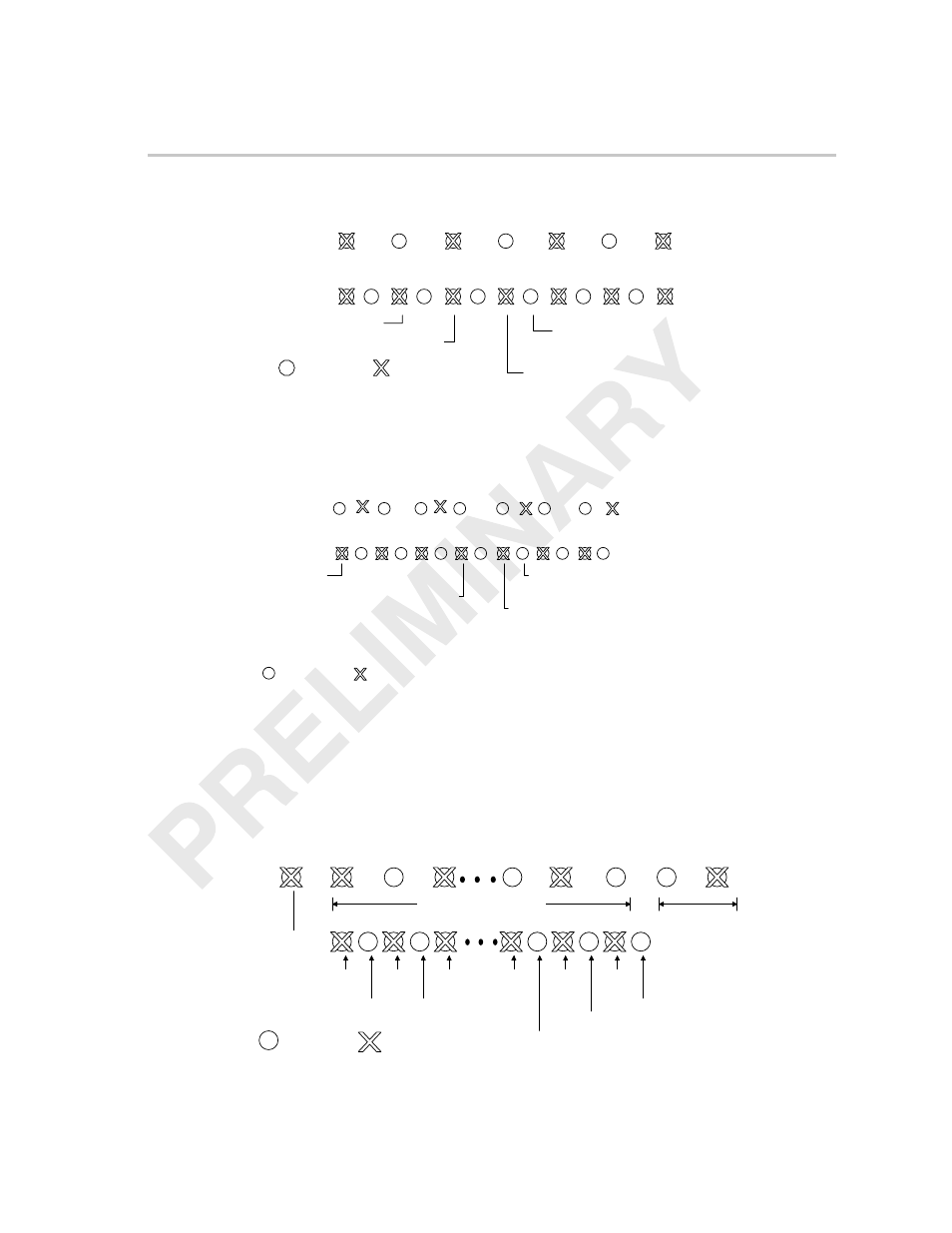
4.4.4
Edge Pixel Replication
Because four tap filters are used on the output, the first and last two pixels on
each line must be mirrored. An example of how the filter uses the mirrored pixels
for the luminance filter (2
×
co-sited) is shown in Figure 4–22.
Figure 4–22. Output Edge Pixel Replication
a
–
–
a’
b
b’
c
a
n–1’
n
n’
n–2 n–2’ n–1
a
b
c
n
n–2
n–1
Horizontal Image Size
Leading edge
replicated pixel
Trailing edge
replicated pixels
n
n–1
Y’a = Ya Y’b = Yb Y’c = Yc
Y’n–2 =
Yn–2
Y’n–1 =
Yn–1
Y’n = Yn
Y’a’ = ƒ(Ya’, Ya’, Yb’, Yc)
Y’b’ = ƒ(Ya’, Yb’, Yc’, Yd)
Y’n’ = ƒ(Yn–1, Yn, Yn, Yn–1)
Y’n–2’ = ƒ(Yn–3, Yn–2, Yn–1’, Yn)
Y’n–1’ = ƒ(Yn–2, Yn–1, Yn’, Yn)
Luma (Y)
sample
Chroma (Cb/Cr)
samples