I/o board – NEC 140He User Manual
Page 37
2-9
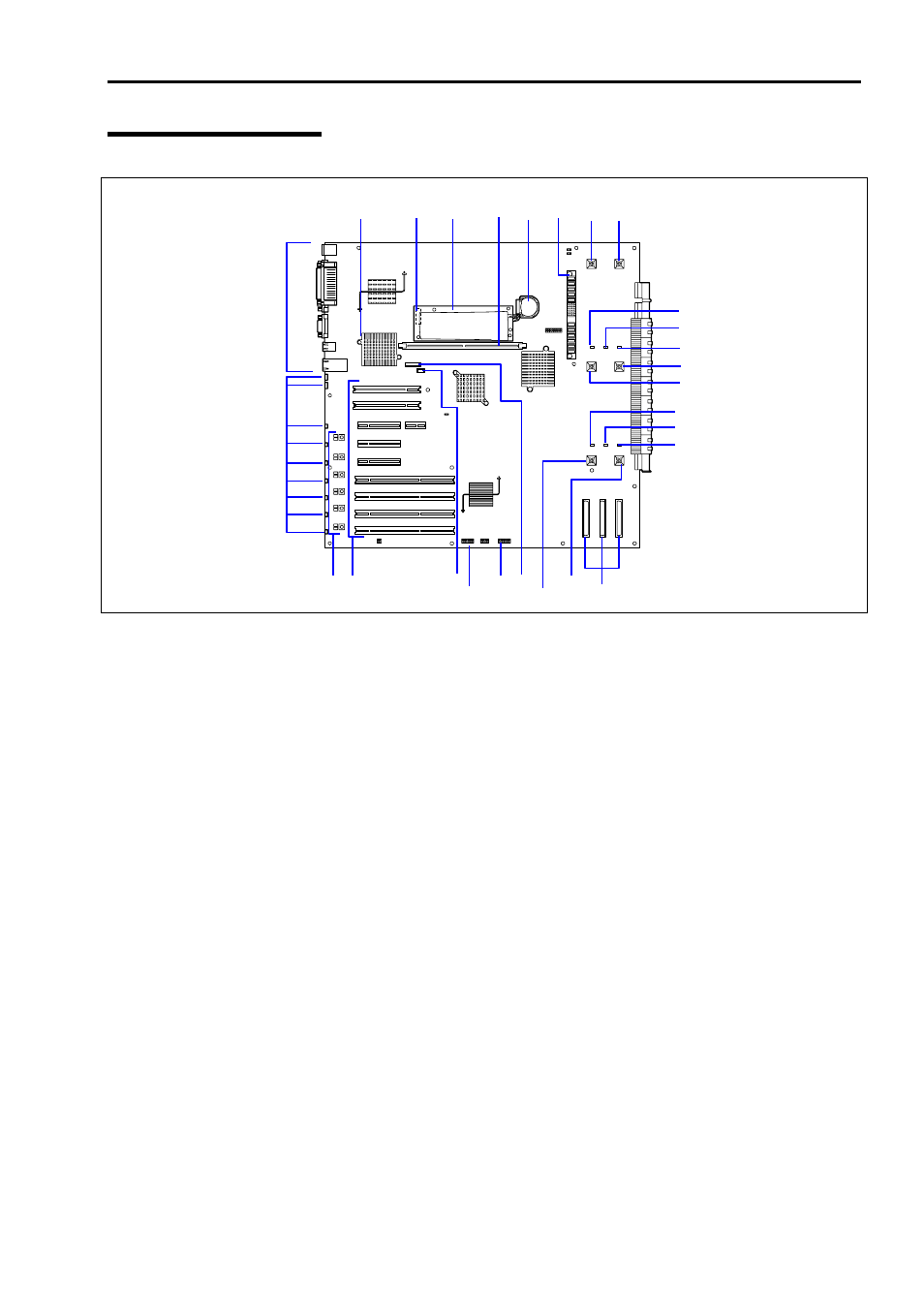
I/O Board
1
Connectors for external devices
2
PCI slot error lamp (corresponds to PCI slots #1 to #9 from top)
3
PCI slot power lamp (upper) / PCI slot Fault lamp (lower)
(corresponds to PCI slots #4 to #9 from top)
4
PCI board slot (PCI slots #1 to #9 from top)
Slots 1, 2: Non-hot-plug PCI, 5V, 33MHz
Slot 3: Non-hot-plug PCI-Express (x4)
Slots 4 and 5: (Hot-plug PCI-Express (x8)
Slots 6 to 9: Hot-plug PCI-X, 3.3V, 100MHz
5 IPMB
connector
6
BMC configuration jumper block
7
Jumper switch for CMOS/Password clear
8
Management LAN board connector
9 Fan
connector
Number following the bold-faced number indicates port number.
10 SCSI
connector
Ch-2, Ch-1, and HDD cage from left
11
Fan error lamp
Number following the bold-faced number indicates fan number.
12
Power BP connector
13 Lithium
battery
14
DIMM connector for RAID
15
NiMH battery module for RAID
16 Battery
module
connector
17 LAN
controller
9-4
1
2
3 4
5
7 8
10
11-1
11-4
11-5
9-5
9-2
11-2
11-3
11-6
17
16
15
14
12
9-6 9-3
13
9-1
6