Front view (with the front door open) – NEC 140He User Manual
Page 32
2-4
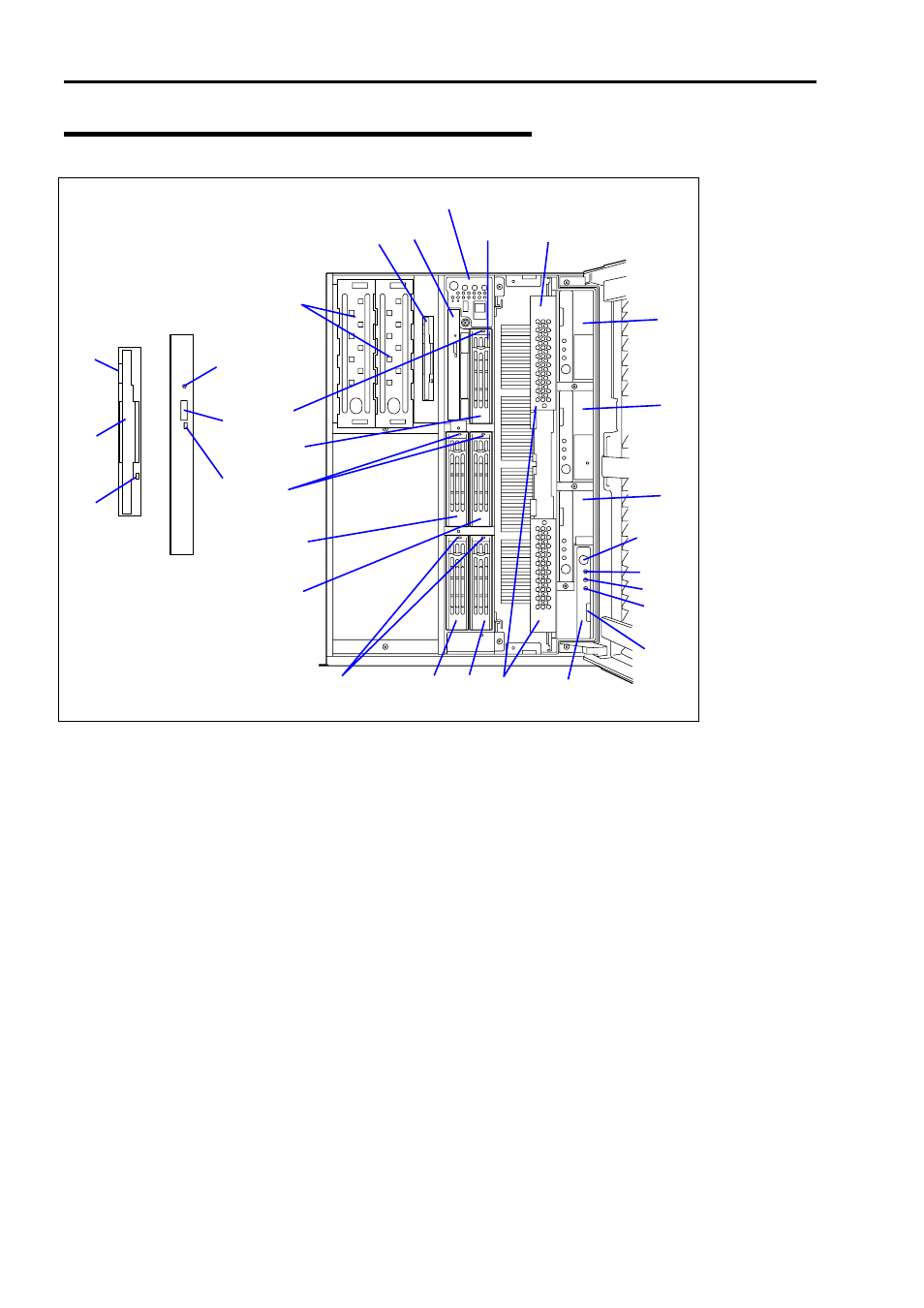
Front View (with the Front Door Open)
1
3.5-inch floppy disk drive
Insert a 3.5-inch floppy disk to the 3.5-inch floppy disk drive to read data from the disk or write data to the disk.
1-1: Eject button
1-2: Disk slot
1-3: Floppy disk access lamp (lits green when accessing)
2 CD-ROM
drive
See "Lamps" described later.
The CD-ROM drive reads data from the inserted CD-ROM.
2-1: Emergency eject hole - 2-2: CD Tray eject button - 2-3: Access lamp lits orange when accessing)
3
3.5-inch disk bay
The 3.5-inch hard disk bay contains additional hard disk slots. Hard disk drives having the thickness of 1 inch can
be inserted into the slots. The number following the bold-faced character indicates the SCSI ID.
4 DISK
lamp
5 Processor
board
5-1: Processor board ejector
6 Memory
board
6-1: Memory board ejector - 6-2: Memory board power lamp - 6-3: Memory board attention lamp
6-4: Memory board redundancy lamp - 6-5: Memory board attention switch
7
Additional memory board slot
The number following the bold-faced character indicates the slot number.
Additional memory board shall be installed in the slot #2, #3, and then #4 in this order.
8
5.25-inch device bay
DAT (digital audio tape) drive or optical disk drive may be installed in the 5.25-inch device bays. Slot #1 (right)
and slot #2 (left).
9
Additional 3.5-inch disk bay
Install the optional HotSwap HDD cage 3-drive SCSI Media Bay in this bay. With the cage, up to thirteen hard
disk drives can be connected to the server.
2
-1
2
-2
2
-3
1
-2
1
-3
1
-1
4
1
2
3
5
8
7-3
7-4
4
3
-0
4
7-2
6
-5
3
-1
3
-2
3
-3
3
-4
5
-1
6
6
-1
6
-2
6
-3
6
-4