Figure 4-4. current calibration window, Current calibration window -8 – KEPCO KLP Series User Manual, Rev 4 User Manual
Page 88
4-8
KLP 091313
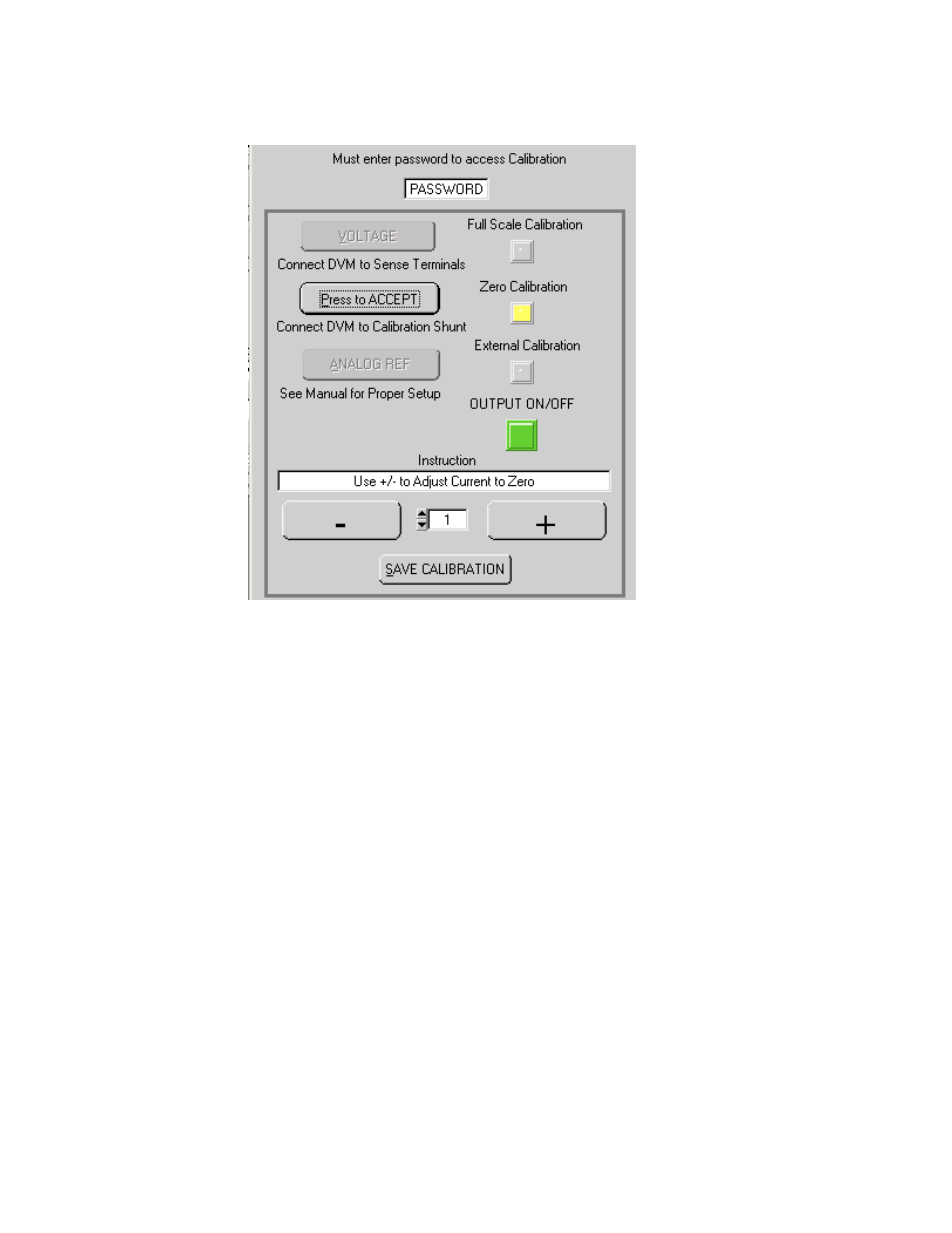
FIGURE 4-4. CURRENT CALIBRATION WINDOW
2. Monitor DVM and click the “+” button to increase and the “–“ to decrease the output current
until the DVM reads as close as possible to maximum rated current (Calculate current as fol-
lows
:
I (Amperes) = DVM reading (Volts) / Shunt Resistance (Ohms).
3. Click the PRESS TO ACCEPT button to accept the value. The status display reads C_0
.
Click the “+” button to increase and the “–“ to decrease the output current until the DVM
reads as close as possible to minimum positive or zero current (Calculate current as follows:
(Amperes) = DVM reading (Volts) / Shunt Resistance (Ohms).
4. Click the PRESS TO ACCEPT button to accept the value. The status display reads CMAX.
Click the “+” button to increase and the “–“ to decrease the output current until the DVM
reads as close as possible to maximum rated current (Calculate current as follows:
I (Amperes) = DVM reading (Volts) / Shunt Resistance (Ohms).
5. Click the Press to ACCEPT button to accept the value; the status display now reads OUTC.
At the ANALOG I/O PORT J2, connect the DVM to CURR_RBACK and GND as shown in
Figure 4-1. Click the “+” button to increase and the “–“ to decrease the output current until
the DVM reads as close as possible to 10V.