8 feedback loss detection, Feedback loss detection – Yaskawa iQpump Drive User Manual User Manual
Page 83
4.8 Feedback Loss Detection
YASKAWA TM.iQp.01 iQpump Drive User Manual
83
4.8
Feedback Loss Detection
◆ b5-12, b5-13, b5-14
Table 4.15
The iQpump drive offers a feedback signal loss detection function in case the connected feedback device fails or a problem with the
wiring occurs.
■
b5-12 PI Feedback Reference Missing Detection Selection
Factory default setting: 0: (Disabled)
To enable feedback loss detection, program parameter b5-12 to a value greater than 0 and b5-13 Feedback Loss Detection Level to the
minimum feedback level for normal operation.
b5-13 Feedback Loss Detection Level Range: 0 to 100%
b5-14 Feedback Loss Detection Time Range: 0.0 to 25.5 sec. (1.0 Factory Default)
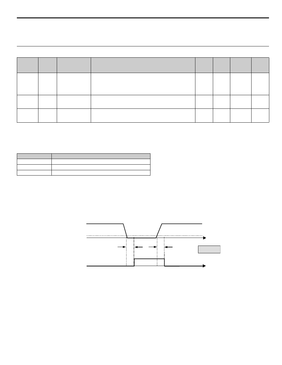
Figure 4.8 Loss of PI Feedback Feature
Example: Constant Pressure System
Pressure Transducer: 150 PSI (4 ~ 20mA)
Desired Operation:
Feedback Loss Fault when pressure falls below 15 PSI for more than 5.0 sec.
Solution:
Program b5-12 to 2 Feedback Loss Detection Fault
Program b5-13 to 10% (15 PSI divided by 150 PSI times 100% = 10%)
Program b5-14 to 5.0 sec.
Parameter
No.
Modbus
Address
Parameter Name
Digital Operator
Display
Description
Setting
Range
Factory
Setting
Menu
Location
Page
No.
b5-12
01B0H
PI Feedback
Reference
Missing Detection
Selection
Fb los Det Sel
0: Disabled
1: Alarm
2: Fault
0 to 2
0
Programming
b5-13
01B1H
PI Feedback Loss
Detection Level
Fb los Det Lvl
Sets the PI feedback loss detection level as a percentage of maximum
frequency (E1-04).
0 to 100
0%
Programming
b5-14
01B2H
PI Feedback Loss
Detection Time
Fb los Det Time
Sets the PI feedback loss detection delay time in terms of seconds.
0.0 to 25.5
1.0 sec Programming
Setting
Description
0
Disabled (factory default)
1
Alarm
2
Fault
Measured
Feedback
T
t
Feedback
Loss Output
T
b5-13
T = b5-14
Feedback
Loss Digital Output
ON (CLOSED)
OFF (OPEN)
TIME