6 low feedback level alarm and fault setup, Low feedback level alarm and fault setup, Low feedback – Yaskawa iQpump Drive User Manual User Manual
Page 79: Lfb/lw
4.6 Low Feedback Level Alarm and Fault Setup
YASKAWA TM.iQp.01 iQpump Drive User Manual
79
4.6
Low Feedback Level Alarm and Fault Setup
◆ P1-07, P1-08, P1-13
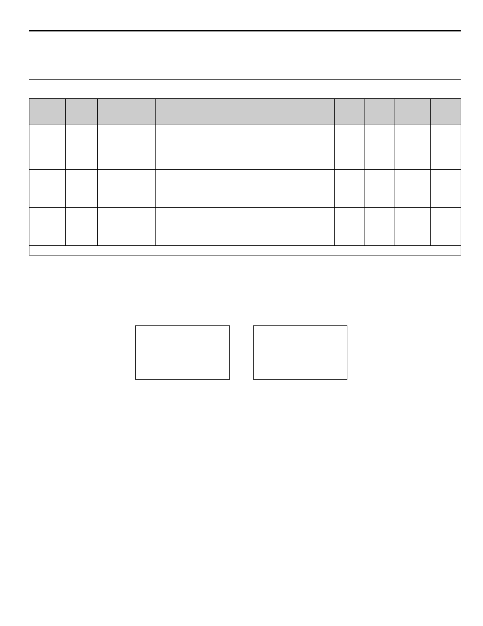
Table 4.13
The iQpump drive continuously monitors the systems feedback device and has the ability to show an alarm or even fault the iQpump
drive when the feedback signals fall below a programmed low feedback level (P1-07) for a programmed low feedback level fault delay
time (P1-08).
The hysteresis level (P1-13) determines the low feedback alarm turn-off level. In case of a low feedback alarm, the alarm message will
turn-off when the feedback level rises above the programmed low feedback level (P1-07) plus the hysteresis level (P1-13).
Figure 4.1
Figure 4.4 Low Feedback Alarm and Fault Displays
Parameter
No.
Modbus
Address
Parameter Name
Digital Operator
Display
Description
Setting
Range
Factory
Setting
Menu
Location
Page
No.
P1-07
0606H
Low Feedback Level
Low FB Level
The Drive will display a “Low Feedback (LFB)” alarm when the
feedback level falls below the programmed level. The alarm will turn
off when the feedback level rises above the programmed Low
Feedback Level plus the Hysteresis Level (P1-13). A value of 0
disables this function. This function is only active during running
while operating in the auto mode.
0.0 to
6000.0
(system
units
P1-02)
0.0
(system
units
P1-02)
Pump Quick
Setup
—
P1-08
0607H
Low Feedback Level
Fault Delay Time
Low Lvl FLT Time
The Drive will display a “Low Feedback/Water (LFB/LW)” alarm
when the feedback level falls below the programmed level for a time
specified in P1-08. The Drive will coast to a stop when a fault occurs.
A value of 0 disables this function. This function is only active
during running while operating in the auto mode.
0 to 3600
sec
5 sec
Pump Quick
Setup
—
P1-13
0108H
Hysteresis Level
Hysteresis Level
Hysteresis Level used for low and high feedback alarm detection. See
function P1-07 and P1-09.
0.0 to
100.0
(system
units
P1-02)
0.0
(system
units
P1-02)
Pump Quick
Setup
—
Denotes that parameter can be changed when the Drive is running.
Low Feedback Alarm
Low Feedback Fault
-DRIVE-
Low Feedback
Low FBK Sensed
Rdy
-DRIVE-
Low FB / Water
LFB/LW
U2-04 =
U2-05 =
0.00 Hz
0.00 A