1 fault detection, Fault detection, Warning – Yaskawa iQpump Drive User Manual User Manual
Page 136
6.1 Fault Detection
136
YASKAWA TM.iQp.01 iQpump Drive User Manual
6.1
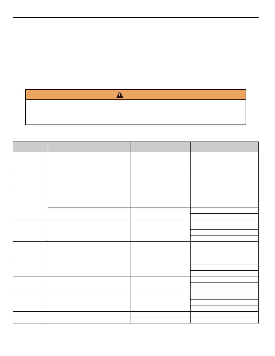
Fault Detection
When the iQpump drive detects a fault, the fault information is displayed on the digital operator, the fault contact closes, and the motor
coasts to stop. (However, a fault with selectable stopping method will operate according to the stopping method selected.)
• If a fault occurs, take appropriate action according to the table by investigating the cause.
• To restart, reset the fault with any of the following procedures:
• Turn ON the fault reset signal.
• Set “14: Fault Reset” to a multi-function digital input (H1-01 to H1-05).
• Press the RESET key of the digital operator.
• Shut off the iQpump drive input power once, and then turn on again.
Table 6.1 Fault Displays and Processing
WARNING
The Run Command (Start Command) needs to be removed prior to resetting a fault. Resetting a fault by removing and
reapplying power to the iQpump drive while the Run Command is applied, may cause the iQpump drive to start
unexpectedly. Therefore, make sure all personnel are clear from the iQpump drive, motor, and machine prior to resetting
the iQpump drive.
Digital
Operator Display
Description
Cause
Corrective Action
BUS
Option Com Err
Option Communication Error
After initial communication was established, the
connection was lost.
Connection is broken, master has
stopped communicating.
Check all connections, verify all user-
side software configurations.
CE
Memobus Com Err
Modbus Communication Error
Control data was not received correctly for two
seconds.
Connection is broken, master has
stopped communicating.
Check all connections, verify all user-
side software configurations.
CPF00
COM-
ERR(OP&INV)
Operator Communication Fault 1
Transmission between the iQpump and the digital
operator cannot be established within 5 seconds
after supplying power.
Digital operator cable not securely
connected, digital operator
defective, control board defective.
Remove the digital operator once and
then reinstall it.
External RAM of CPU is defective.
Control circuit damage.
Cycle power off and on to the iQpump.
Replace the iQpump.
CPF01
COM-
ERR(OP&INV)
Operator Communication Fault 2
After communication started with the digital
operator, a communication fault occurred for 2
seconds or more.
Digital operator cable not securely
connected, digital operator
defective, control board defective.
Remove the digital operator once and
then reinstall it.
Cycle power off and on to the iQpump.
Replace the iQpump.
CPF02
BB Circuit Err
Baseblock Circuit Fault
Baseblock circuit fault at power-up.
Gate array hardware failure during
power-up.
Perform a factory initialization.
Cycle power off and on to the iQpump.
Replace the control board.
CPF03
EEPROM Error
EEPROM Fault
EEPROM fault, check sum not valid.
Noise or spike on the control
circuit input terminals.
Perform a factory initialization.
Cycle power off and on to the iQpump.
Replace the control board.
CPF04
Internal A/D Err
CPU Internal A/D Converter Fault
Noise or spike on the control
circuit input terminals.
Perform a factory initialization.
Cycle power off and on to the iQpump.
Replace the control board.
CPF05
External A/D Err
CPU External A/D Converter Fault
Noise or spike on the control
circuit input terminals.
Perform a factory initialization.
Cycle power off and on to the iQpump.
Replace the control board.
CPF07
RAM-Err
ASIC Internal RAM Fault
(RAM)
—
Cycle power off and on to the iQpump.
Control circuit damage.
Replace the iQpump.