2 iqpump drive start up procedures, Iqpump drive start up procedures, Warning – Yaskawa iQpump Drive User Manual User Manual
Page 69
4.2 iQpump Drive Start Up Procedures
YASKAWA TM.iQp.01 iQpump Drive User Manual
69
4.2
iQpump Drive Start Up Procedures
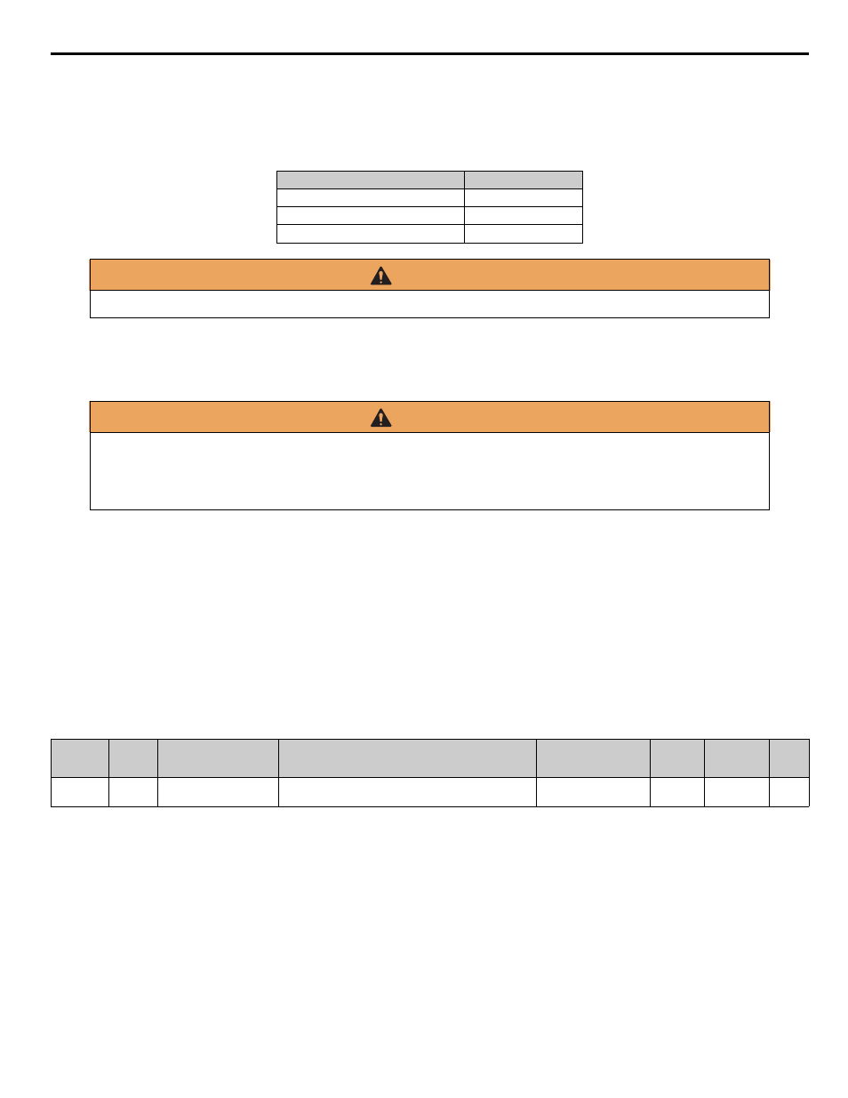
1. Confirm that all three phases are present and that the input voltage is correct for the iQpump drive being set up.
Measure the voltage on the line side of the iQpump drive’s Molded Case Circuit Breaker/disconnect and record below.
Table 4.1
2.
If voltage level is within iQpump drive Specification (See Appendix C), APPLY POWER to energize the iQpump drive. The
STOP, AUTO SEQ and AUTO REF indicators should be on.
3.
REMOVE POWER from the iQpump drive. Wait for the Red CHARGE LED (near the power terminals) to go out.
4. Connect the motor leads to the iQpump drive at terminals U/T1, V/T2 and W/T3.
5. APPLY POWER to the iQpump drive.
6. Press the HAND key once. This puts the iQpump drive in the Hand Mode, allowing run/stop and speed commands (frequency
references) by the digital operator. The AUTO SEQ and AUTO REF indicators turn off. The FWD light turns on. The RUN
light turns on. The STOP light is blinking. “Hand Reference” (U1-01) is now displayed on the Digital Operator.
7. Press the OFF key.
8. Press the MENU key two times. Press the DATA/ENTER key once to enter the Pump Quick Setup Menu. Press the S key to
display parameter E1-01 “Input Voltage.” This parameter selects the nominal input voltage the iQpump drive will receive. To set
this parameter for the application. Press the DATA/ENTER key once. Use the
S,T, and X keys and the DATA/ENTER key to
set this parameter per the application.
Table 4.2 Input Voltage Setting
Ensure the DATA/ENTER key is pressed to enter the selection in the iQpump drive. “Entry Accepted” briefly appears and the
display is now no longer flashing.
9. Press the S key once to display E2-01 “Motor Rated FLA.”
This parameter is the foundation of motor protection. It can be entered when auto-tuning is performed. Set this parameter
according to the motor rated current (FLA). Press the DATA/ENTER key once. Use the S,T, and X keys to adjust E2-01 to
the motor rated full load amps.
Measurement Location
Voltage (Vac)
L1 – L2
L2 – L3
L1 – L3
WARNING
Use extreme caution when performing measurements as contact with live parts may result in personal injury or death.
WARNING
The internal capacitor remains charged even after the power supply is turned off. The status indicator LED’s and the
digital operator display will be extinguished when the DC bus voltage is below 50VDC. To prevent electric shock, wait
at least 5 minutes after all indicators are off and measure the DC Bus voltage level to confirm a safe level prior to
working on the iQpump drive.
Parameter
No.
Modbus
Address
Parameter Name
Digital Operator
Display
Description
Setting Range
Factory
Setting
Menu
Location
Page
No.
E1-01
0300H
Input Voltage Setting
Input Voltage
Set to the nominal voltage of the incoming line.
155 to 255.0 (240 V)
310 to 510.0 (480 V)
240 V
480 V
Pump Quick
Setup