7 high feedback level alarm and fault setup, High feedback level alarm and fault setup, High feedback – Yaskawa iQpump Drive User Manual User Manual
Page 81
4.7 High Feedback Level Alarm and Fault Setup
YASKAWA TM.iQp.01 iQpump Drive User Manual
81
4.7
High Feedback Level Alarm and Fault Setup
◆ P1-09, P1-10, P1-13
Table 4.14
The iQpump drive continuously monitors the systems feedback device and has the ability to show an alarm and/or fault the iQpump drive
when the feedback signals rise above a programmed high feedback level (P1-09) for a programmed high feedback level fault delay time
(P1-10).
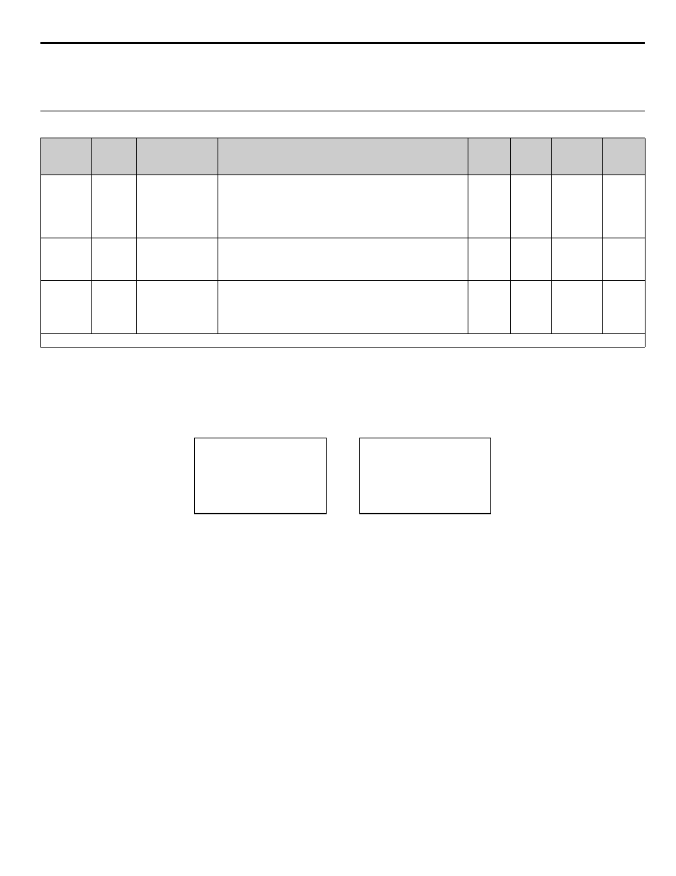
The hysteresis level (P1-13) determines the high feedback alarm turn-off level. In case of a high feedback alarm, the alarm message will
turn-off when the feedback level falls below the programmed high feedback level (P1-09) minus the hysteresis level (P1-13).
Figure 4.6 High Feedback Alarm and Fault Displays
Parameter
No.
Modbus
Address
Parameter Name
Digital Operator
Display
Description
Setting
Range
Factory
Setting
Menu
Location
Page
No.
P1-09
0608H
High Feedback Level
High FB Level
The Drive will display a “High Feedback Level (HFB)” alarm when
the feedback level rises above the programmed level. The alarm will
turn off when the feedback level falls below the programmed High
Feedback Level minus the Hysteresis Level (P1-13). This function is
active during running in the hand mode, auto mode, pre-charge and
thrust-bearing mode.
0.0 to
6000.0
(system
units
P1-02)
155.0
(system
units
P1-02)
Pump Quick
Setup
—
P1-10
0609H
High Feedback Level
Fault Delay Time
Hgh Lvl FLT Time
The Drive will initiate a “High Feedback Fault (HFB)” when the
feedback level rises above the programmed level for a time specified
in P1-10. The Drive will coast to a stop when a fault occurs. This
function is active during running in all operation modes.
0 to 3600
2 sec
Pump Quick
Setup
—
P1-13
0108H
Hysteresis Level
Hysteresis Level
Hysteresis Level used for low and high feedback alarm detection. See
function P1-07 and P1-09.
0.0 to
100.0
(system
units
P1-02)
0.0
(system
units
P1-02)
Pump Quick
Setup
—
Denotes that parameter can be changed when the Drive is running.
High Feedback Alarm
High Feedback Fault
-DRIVE-
High Feedback
High FBK Sensed
Rdy
-DRIVE-
High Feedback
HFB
U2-04 =
U2-05 =
0.00 Hz
0.00 A