Operation menu (-drive-), U1 monitor list – Yaskawa iQpump Drive User Manual User Manual
Page 57
3.4 Drive Main Menu
YASKAWA TM.iQp.01 iQpump Drive User Manual
57
◆ Operation Menu (-DRIVE-)
This menu is used for setting a speed command or monitoring values such as output frequency and output current. It is also used for
displaying the fault history and the fault traces. The iQpump drive must be in this menu in order to run, see parameter b1-08.
■
U1 Monitor List
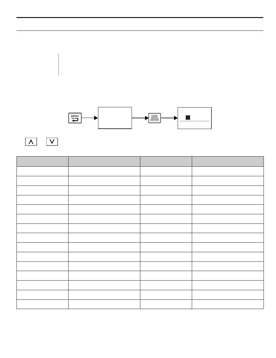
Follow the key operations below (
) to access the Operation Menu:
Figure 3.3 U1 Monitor List Access Procedure
Use
and
keys to scroll through the U1 Monitor Parameter List. See
Appendix A
for functional description.
Table 3.8 U1 Monitor Parameter List
IMPORTANT
• Leaving the iQpump drive in a menu other than the Operation Menu, will prohibit the iQpump drive
from running. While running, if the iQpump drive is in a menu other than “Operation” and the run com-
mand is removed and re-applied, the iQpump drive will stop and will not start until the Operation Menu is
selected unless b1-08 = 1.
Monitor
Parameter Name
Digital Operator Display
Monitor
Parameter Name
Digital Operator Display
U1-01
Auto Setpoint Reference
Auto: Setpoint
U1-24
PI Feedback Value
PI Feedback
U1-02
Output Frequency
Output Freq
U1-28
CPU Number
CPU ID
U1-03
Output Current
Output Current
U1-29
kWh
kWh Lo 4 Digits
U1-06
Output Voltage
Output Voltage
U1-30
MWh
kWh Hi 5 Digits
U1-07
DC Bus Voltage
DC Bus Voltage
U1-34
First Parameter Causing an OPE
OPE Detected
U1-08
Output Power
Output kWatts
U1-36
PI Input
PI Input
U1-10
Input Terminal Status
Input Term Sts
U1-37
PI Output
PI Output
U1-11
Output Terminal Status
Output Term Sts
U1-38
PI Setpoint
PI Setpoint
U1-12
Drive Operation Status
Int Ctl Sts 1
U1-39
Memobus Communication Error Code
Transmit Err
U1-13
Cumulative Operation Time
Elapsed Time
U1-40
Heatsink Cooling Fan Operation Time
FAN Elapsed Time
U1-14
Software Number
FLASH ID
U1-90
Pump Setpoint Reference
Pump Setpoint
U1-15
Terminal A1 Input Voltage
Term A1 Level
U1-91
Pump Feedback
Pump Feedback
U1-16
Terminal A2 Input Voltage
Term A2 level
U1-92
Pump Status
Pump Status
U1-18
Motor Secondary Current (Iq)
Mot SEC Current
U1-93
Total Setpoint Compensation
Total SP Comp.
U1-20
Output Frequency After Soft Start
SFS Output
U1-94
Motor Speed
Motor Speed
-DRIVE-
** Main Menu **
- - - - - - - - - - - - - -
Operation
-DRIVE- Rdy
Frequency Ref
U1-
01
= 0.00Hz
- - - - - - - - - - - - - - - - - - - -
U1-02= 0.00Hz
U1-03= 0.00A
x1
-DRIVE-
U1-02=
Auto Setpoint Ref
U1-
0.00PSI
60.00Hz
U1-91=
0.00PSI
Rdy
01
=