HEIDENHAIN iTNC 530 (340 49x-04) User Manual
Page 427
HEIDENHAIN iTNC 530
427
8.6 Cy
cles f
o
r Milling P
o
c
k
ets, St
uds and Slots
Machining operation (0/1/2)
Q215: Define the
machining operation:
0: Roughing and finishing
1: Only roughing
2: Only finishing
Side finishing and floor finishing are only executed if
the finishing allowances (Q368, Q369) have been
defined.
Slot width
Q219 (value parallel to the secondary axis
of the working plane): Enter the slot width. If you
enter a slot width that equals the tool diameter, the
TNC will carry out the roughing process only (slot
milling). Maximum slot width for roughing: Twice the
tool diameter
Finishing allowance for side
Q368 (incremental
value): Finishing allowance in the working plane.
Pitch circle diameter
Q375: Enter the diameter of
the pitch circle.
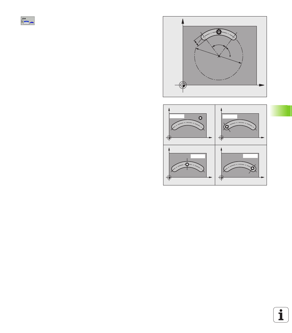
Reference for slot position (0/1/2/3)
Q367:
Position of the slot in reference to the position of the
tool when the cycle is called:
0: The tool position is not taken into account. The slot
position is determined from the entered pitch circle
center and the starting angle.
1: Tool position = Center of left slot circle. Starting
angle Q376 refers to this position. The entered pitch
circle center is not taken into account.
2: Tool position = Center of center line. Starting angle
Q376 refers to this position. The entered pitch circle
center is not taken into account.
3: Tool position = Center of right slot circle. Starting
angle Q376 refers to this position. The entered pitch
circle center is not taken into account.
Center in 1st axis
Q216 (absolute value): Center of
the pitch circle in the reference axis of the working
plane. Only effective if Q367 = 0.
Center in 2nd axis
Q217 (absolute value): Center of
the pitch circle in the minor axis of the working plane.
Only effective if Q367 = 0.
Starting angle
Q376 (absolute value): Enter the polar
angle of the starting point.
Angular length
Q248 (incremental value): Enter the
angular length of the slot.
X
Y
Q248
Q376
Q219
Q375
X
Y
X
Y
X
Y
X
Y
Q367=0
Q367=1
Q367=2
Q367=3