Ch 5 - signal management, Overview, Signal management 5 – Measurement Computing Personal Daq rev.6.0 User Manual
Page 97
Personal Daq User’s Manual
928196
Signal Management 5-1
Signal Management
5
Overview ……5-1
Channel Control and Expansion ……5-3
Signal Acquisition ……5-4
Measurement Duration, Sample Rate, and
Resolution ……5-4
Under Sampling and Aliasing …… 5-4
Triggering ……5-5
Input Isolation ……5-6
Signal Modes ……5-6
System Noise ……5-7
Averaging ……5-7
Analog Filtering ……5-8
Input and Source Impedance ……5-8
Crosstalk ……5-8
Overview
This chapter pertains to signal management, the use of different types of signals, and how to reduce
common noise problems. The final portion of the chapter contains basic troubleshooting tips.
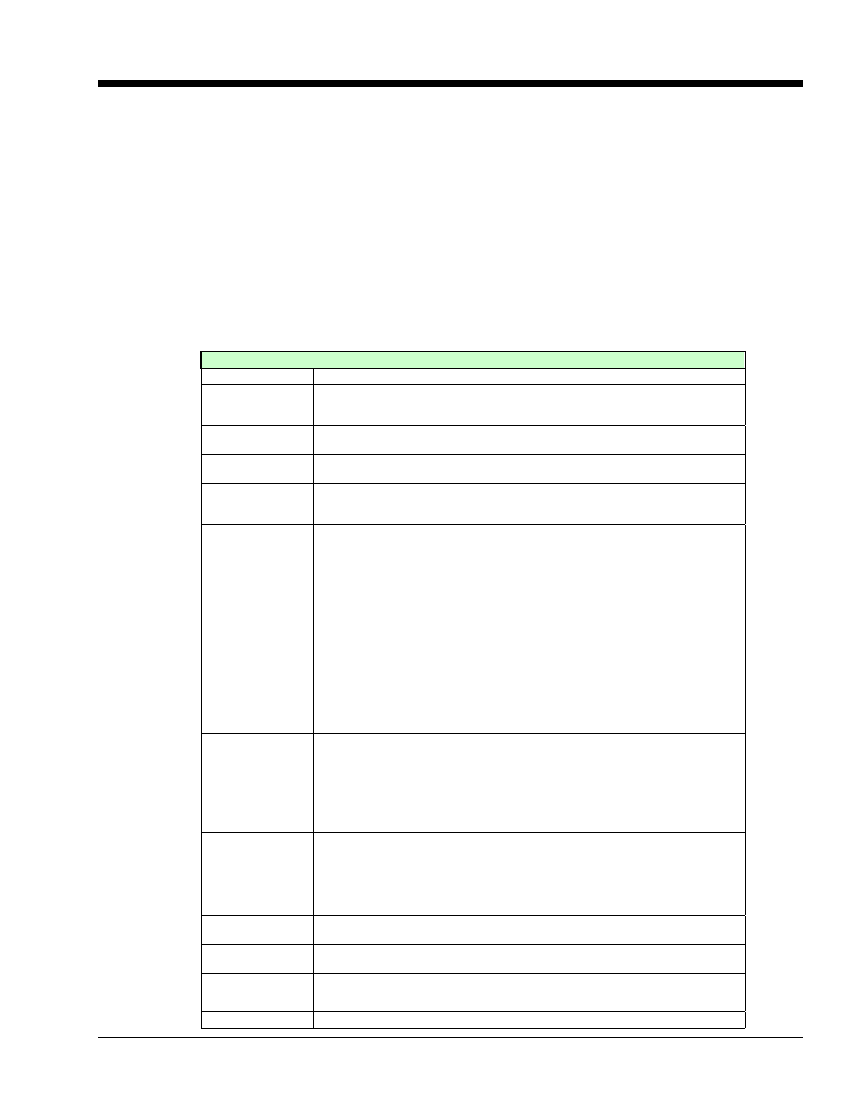
This table defines data acquisition terms, as used in this manual.
Data Acquisition Terms and Meanings
Acquisition
A collection of scans acquired at a specified rate.
Aliasing
A type of error that results from having a scan rate set too low for a given variable
input signal. Depending of the amount of aliasing, a sign wave may appear
jagged, flat, or as a sign wave at a different frequency.
Analog
A signal of varying voltage or current that communicates data. Typical analog
signals have the form of sine waves.
Analog-to-Digital
Converter (ADC)
A circuit or device that converts analog values into digital values, such as binary bits,
for use in digital computer processing.
API
Application Program Interface. The interface program within the Personal Daq
system’s driver that includes function calls specific to Personal Daq hardware and
can be used with user-written programs (several languages supported).
Buffer
Buffer refers to a circuit or device that allows a signal to pass through it, while
providing isolation, or another function, without altering the signal. Buffer usually
refers one of the following:
(a) A device or circuit, which allows for the temporary storage of data during data
transfers. Such storage is often necessary to compensate for differences in
data flow rates. A FIFO (First In - First Out) buffer is one in which the data that
is stored first, is also the first data to leave the buffer.
(b) A follower stage, which is used to drive a certain number of gates without
overloading the proceeding, stage.
(c) An amplifier which accepts high source impedance input and results in low
source impedance output (effectively, an impedance buffer).
(d) Buffer Amplifier (see Buffer Amplifier).
Buffer Amplifier
An amplifier used primarily to match two different impedance points, and isolate one
stage from a succeeding stage in order to prevent an undesirable interaction
between the two stages. (Also see Buffer).
Channel
In reference to Personal Daq, channel simply refers to a single input, or output entity.
In a broader sense, an input channel is a signal path between the transducer at the
point of measurement and the data acquisition system. A channel can go through
various stages (buffers, multiplexers, or signal conditioning amplifiers and filters).
Input channels are periodically sampled for readings.
An output channel from a device can be digital or analog. Outputs can vary in a
programmed way in response to an input channel signal.
Common mode
voltage
Common mode voltage refers to a voltage magnitude (referenced to a common
point) that is shared by 2 or more signals. Example: Signal 1 is +5VDC
referenced to common. Signal 2 is +6VDC referenced to common. The common
mode voltage for the two signals is ((5 + 6)
÷2), or +5.5 VDC
Common mode pertains to signals that are identical in amplitude and duration; and
can be used in reference to signal components.
Crosstalk
An undesired transfer of signals between systems or system components. Crosstalk
causes signal interference, more commonly referred to as noise.
Digital
A digital signal is one of discrete value, in contrast to a varying signal. Digital data is
represented by combinations of binary digits (0s and 1s).
Digital-to-Analog
Converter (DAC)
A circuit or device that converts digital values (binary bits), into analog signals.