Triggering – Measurement Computing Personal Daq rev.6.0 User Manual
Page 101
Note:
Frequency channels will read frequency regardless of the scan rate. Personal Daq circuitry reads a
pulse count and timer count during each scan.
The following table provides general advice regarding the selection of measurement duration. The
concepts are further illustrated by the figure, Examples of Under Sampling.
Analog Input Signal
Variability
Measurement
Duration
Sample
Rate
Resolution
Steady, or gradual
change
Long low
high
Highly variable
(unsteady)
Short high
low
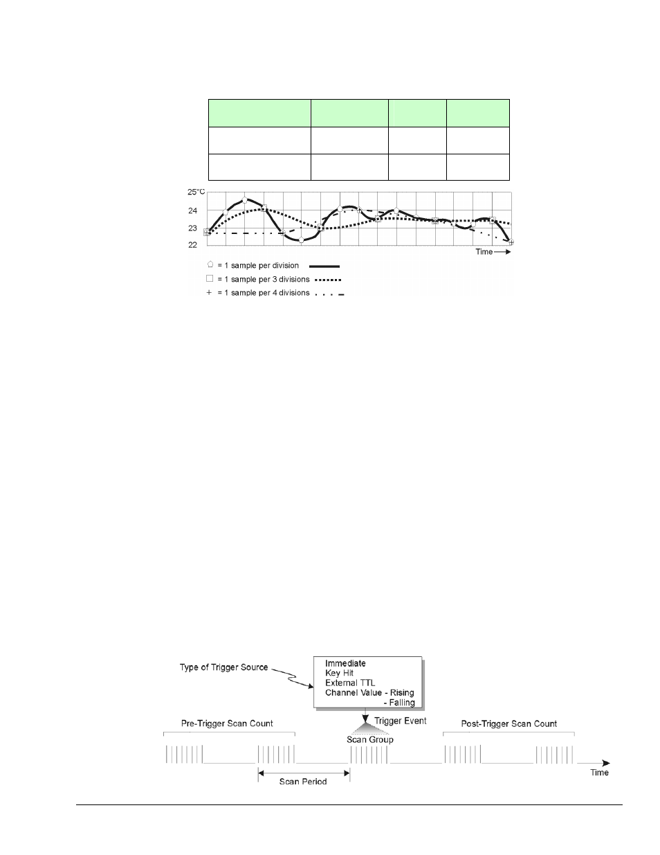
Examples of Under Sampling
The above figure depicts three signals from the same temperature fluctuations. Under Sampling (aliasing)
is evident in two of the signals. Elaboration follows:
Signal 1 – This signal, based on 1 sample per division, is represented by a heavy solid line and
sample-points designated by polygon symbols. The signal represented is a fairly accurate portrayal of the
actual temperature fluctuations.
Signal 2 – This signal, based on 1 sample every 3 divisions, is represented by a heavy dotted line and
sample-points designated by squares. Under sampling has resulted in a distortion, in effect, a lower
amplitude than that exhibited by the first signal, even though each measured point is accurate.
Signal 3 – This signal, based on 1 sample every 4 divisions, is represented by a dotted/dashed line and
sample-points designated by plus signs (+). Fewer samples (a greater degree of under sampling) has
resulted in a further distortion and lowering of signal amplitude.
From these examples it should be realized that more samples will result in a more accurate representation
of the actual signal, and that under sampling will tend to lower the amplitude of the signal, exhibiting a
trend toward a “flat line” state.
As stated earlier, the more variability a signal has, the more samples that are needed to accurately portray
it.
Triggering
Triggering controls an acquisition cycle. Once the system is armed, a trigger is required to collect the data.
Typically, three data collection parameters are specified: the pre-trigger count, the post-trigger scan count,
and the trigger source. The user must determine the triggering requirement based on the nature of the
measurement and the amount of data needed to satisfy the system’s purpose.
Personal Daq User’s Manual
878695
Signal Management 5-5