5 synchronous 8/16 bit µcontroller interface, 1 interface, 2 configuration – BECKHOFF ET1100 User Manual
Page 88: Synchronous 8/16 bit µcontroller interface, Interface, Configuration, Table 69: µcontroller signals, Figure 28: µcontroller interconnection
PDI description
III-74
Slave Controller
– ET1100 Hardware Description
6.5
Synchronous 8/16 bit µController Interface
6.5.1
Interface
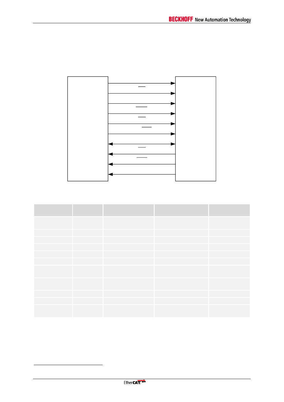
The synchronous µController interface uses demultiplexed address and data busses. The bidirectional
data bus can be either 8 bit or 16 bit wide. The signals of the synchronous µController interface of
EtherCAT devices are:
8/16 bit
µController
(sync)
CS
ADR
BHE
DATA
TA
EtherCAT
device
IRQ
RD/WR
TS
CPU_CLK_IN
EEPROM_LOADED
Figure 28: µController interconnection
4
Table 69: µController signals
Signal
sync I/F
Signal
async I/F
Direction
Description
Signal polarity
CPU_CLK_IN
N/A
IN
(µC → ESC)
µController interface
clock
CS
CS
IN
(µC → ESC)
Chip select
Typical: act. low
ADR[15:0]
ADR[15:0]
IN
(
µC → ESC)
Address bus
act. high
BHE
BHE
IN
(µC → ESC)
Byte High Enable
Typical: act. low
TS
RD
IN
(µC → ESC)
Transfer Start
Typical: act. low
RD/nWR
WR
IN
(µC → ESC)
Read/Write access
DATA[15:0]
DATA[15:0]
BD
(µC
↔ ESC)
Data bus for 16 Bit
µController interface
act. high
DATA[7:0]
DATA[7:0]
BD
(µC
↔ ESC)
Data bus for 8 Bit
µController interface
act. high
TA
BUSY
OUT
(ESC → µC)
Transfer Acknowledge
Typical: act. low
IRQ
IRQ
OUT
(ESC → µC)
Interrupt
Typical: act. low
EEPROM_
LOADED
EEPROM_
LOADED
OUT
(ESC → µC)
PDI is active,
EEPROM is loaded
act. high
6.5.2
Configuration
The 16 bit synchronous µController interface is selected with PDI type 0x0A in the PDI control register
0x0140, the 8 bit synchronous µController interface has PDI type 0x0B. It supports different
configurations, which are located registers 0x0150
– 0x0153.
4
All signals are denoted with typical polarity configuration.