2 digital i/o interface, 1 interface, 2 configuration – BECKHOFF ET1100 User Manual
Page 63: Digital i/o interface, Interface, Configuration, Table 54: et1100 digital i/o signals, Figure 9: et1100 digital i/o signals
PDI description
Slave Controller
– ET1100 Hardware Description
III-49
6.2
Digital I/O Interface
6.2.1
Interface
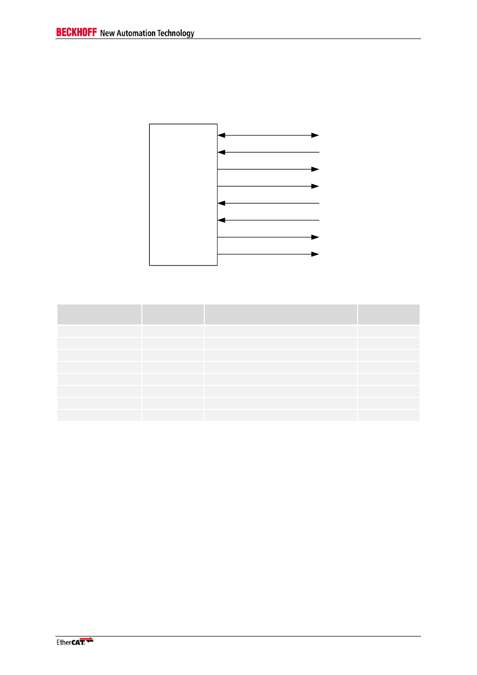
The Digital I/O PDI is selected with PDI type 0x04. The signals of the Digital I/O interface are:
ET1100
I/O[31:0]
LATCH_IN
OUTVALID
SOF
OE_EXT
OE_CONF
WD_TRIG
EEPROM_LOADED
Figure 9: ET1100 Digital I/O signals
Table 54: ET1100 Digital I/O signals
Signal
Direction
Description
Signal
polarity
I/O[31:0]
IN/OUT/BIDIR
Input/Output or Bidirectional data
LATCH_IN
IN
External data latch signal
act. high
OUTVALID
OUT
Output data is valid/Output event
act. high
SOF
OUT
Start of Frame
act. high
OE_EXT
IN
Output Enable
act. high
OE_CONF
IN
Output Enable Configuration
WD_TRIG
OUT
Watchdog Trigger
act. high
EEPROM_LOADED
OUT
PDI is active, EEPROM is loaded
act. high
6.2.2
Configuration
The Digital I/O interface is selected with PDI type 0x04 in the PDI control register 0x0140. It supports
different configurations, which are located in registers 0x0150
– 0x0153.