5 mii management pins, 6 distributed clocks sync/latch pins, Mii management pins – BECKHOFF ET1100 User Manual
Page 36: Distributed clocks sync/latch pins, Table 28: mii management pins, Table 29: dc sync/latch pins
Pin Description
III-22
Slave Controller
– ET1100 Hardware Description
3.5
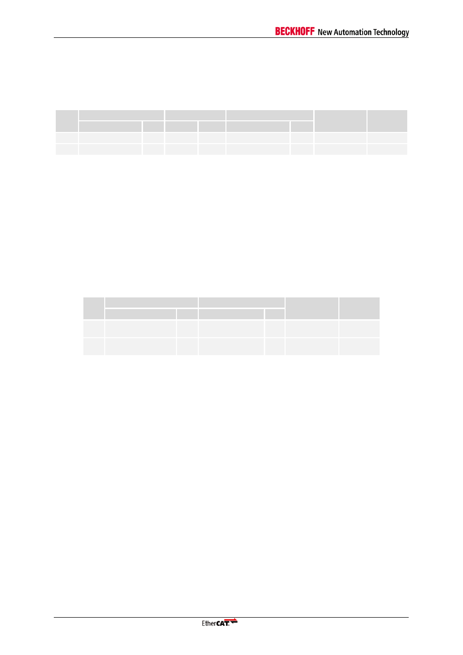
MII Management Pins
The MII Management signals are only used if at least one MII port is configured.
Table 28: MII Management pins
Pin
Pin
No MII port used
MII port(s) used
Configuration
Signal
Internal
PU/PD
Name
Dir.
Signal
Dir.
Signal
Dir.
K11
MI_CLK/LINKPOL
BD
UI
MI_CLK
O
LINKPOL
WPD
K12
MI_DATA
BD
UI
MI_DATA
BD
WPU
MI_CLK/LINKPOL
During power on LINK Polarity configuration during power-up, PHY Management Interface clock
afterwards.
MI_DATA
PHY Management Interface Data.
NOTE: MI_DATA must have a pull-up resistor (4.7 k
Ω recommended for ESCs).
3.6
Distributed Clocks SYNC/LATCH Pins
Table 29: DC SYNC/LATCH pins
Pin
Pin
Signal
Configuration
Signal
Internal
PU/PD
Name
Dir.
Signal
Dir.
E11
SYNC/LATCH[0]
BD
SYNC[0]/
LATCH[0]
O/
I
E12
SYNC/LATCH[1]
BD
SYNC[1]/
LATCH[1]
O/
I
SYNC/LATCH[x]
Distributed Clocks SyncSignal output or LatchSignal input, depending on SII EEPROM configuration.
SYNC/LATCH signals are not driven (high impedance) until the EEPROM is loaded.