5 bidirectional mode, Bidirectional mode, Figure 10: digital output principle schematic – BECKHOFF ET1100 User Manual
Page 65: Ω recommended)
PDI description
Slave Controller
– ET1100 Hardware Description
III-51
32
Output event
configuration
Output register
Digital I/O output
data register
0x0F00:0x0F03
Watchdog
&
&
≥ 1
32
32
32
EOF
DC Sync0
DC Sync1
D
Q
OE_CONF
Digital output pins
OE_EXT
Output event occured
since watchdog active
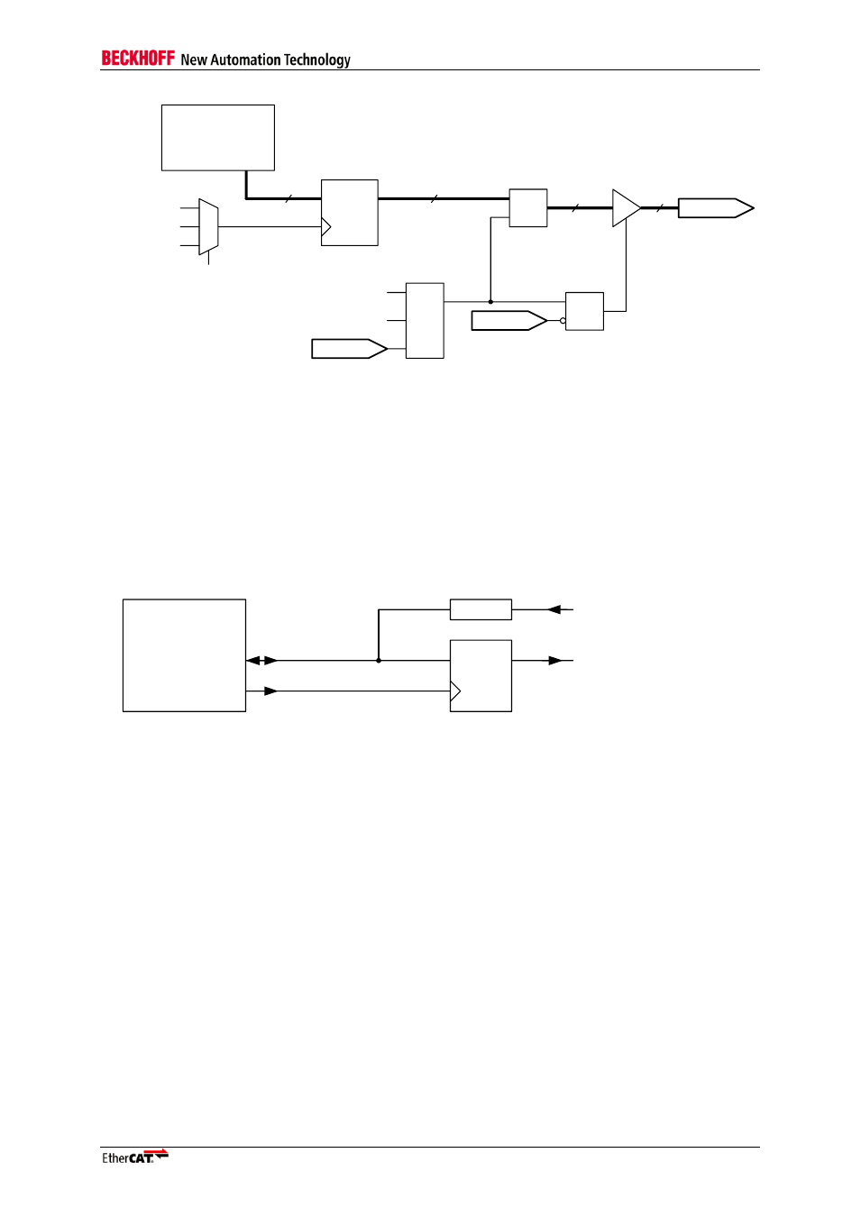
Figure 10: Digital Output Principle Schematic
NOTE: The Digital Outputs are not driven (high impedance) until the EEPROM is loaded. Depending on the
configuration, the Digital Outputs are also not driven if the Watchdog is expired or if the outputs are disabled. This
behavior has to be taken into account when using digital output signals.
6.2.5
Bidirectional mode
In bidirectional mode, all DATA signals are bidirectional (individual input/output configuration is
ignored). Input signals are connected to the ESC via series resistors, output signals are driven actively
by the ESC. Output signals are permanently available if they are latched with OUTVALID (Flip-Flop or
Latch).
EtherCAT
device
Digital Input
Digital Output
DATA
R
OUTVALID
C1
1D
Q
D-FF
Figure 11: Bidirectional mode: Input/Output connection (R=4.7 k
Ω recommended)
Input sample event and output update event can be configured as described in the Digital
Inputs/Digital Outputs chapter.
An output event is signaled by a pulse on OUTVALID even if the digital outputs remain unchanged.
Overlapping input and output events will lead to corrupt input data.