2 power supply, Power supply, Figure 46: et1100 power supply – BECKHOFF ET1100 User Manual
Page 103
Example Schematics
Slave Controller
– ET1100 Hardware Description
III-89
25 MHz
OSC_OUT
OSC_IN
ET1100
Ethernet
PHY
Ethernet
PHY
Ethernet
PHY
CLK25
CLK25
CLK25
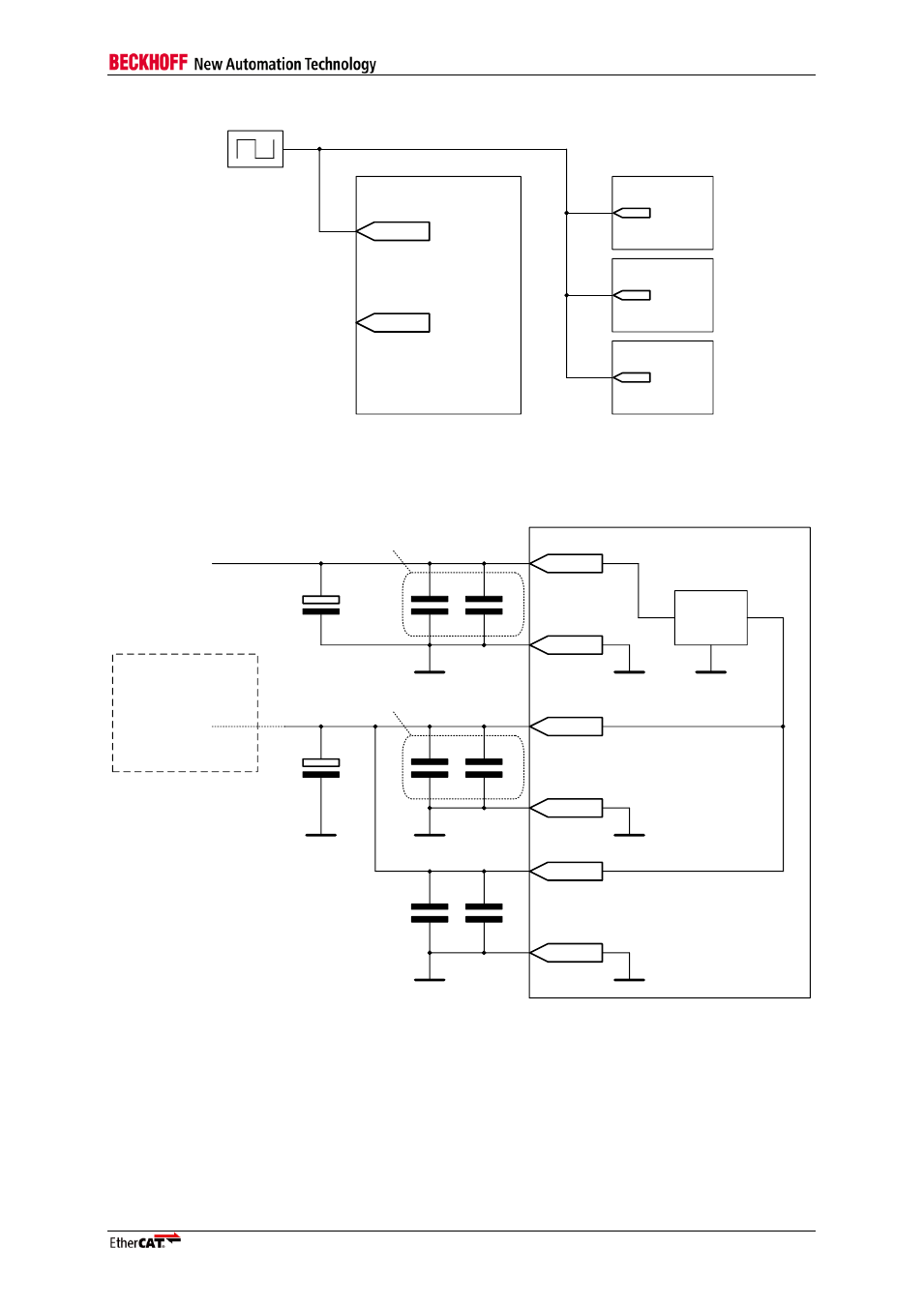
Figure 45: Oscillator clock source for ET1100 and Ethernet PHYs
9.2
Power supply
Optional external
core supply
ET1100
V
CC_PLL
V
CC Core
V
CC I/O
V
CC I/O
GND
PLL
GND
Core
GND
I/O
GND
PLL
GND
Core
GND
I/O
LDO
Vcc Core
V
CC Core Ext
GND
Core
220pF
100 nF
10µF
220pF
100 nF
10µF
220pF
100 nF
For each power pin pair (11x)
For each power pin pair (4x)
Figure 46: ET1100 power supply
Recommendation for voltage stabilization capacitors: 220pF and 100nF ceramic capacitors for each power pin
pair, additional 10µF tantalum electrolytic capacitor for V
CC I/O
, and V
CC Core
/V
CC PLL
, i.e., a total of two 10µF
capacitors.
GND
I/O
, GND
Core
, and GND
PLL
can be connected to a single GND potential.
The internal LDO is self-deactivating if the actual V
CC Core
/V
CC PLL
voltage is higher than the nominal
LDO output voltage.