3 tx shift compensation, Tx shift compensation, Table 50: tx shift timing characteristics – BECKHOFF ET1100 User Manual
Page 59: Figure 6: tx shift timing diagram, Parameter comment t, 25 mhz clock source period (osc_in, see f
MII Interface
Slave Controller
– ET1100 Hardware Description
III-45
4.3
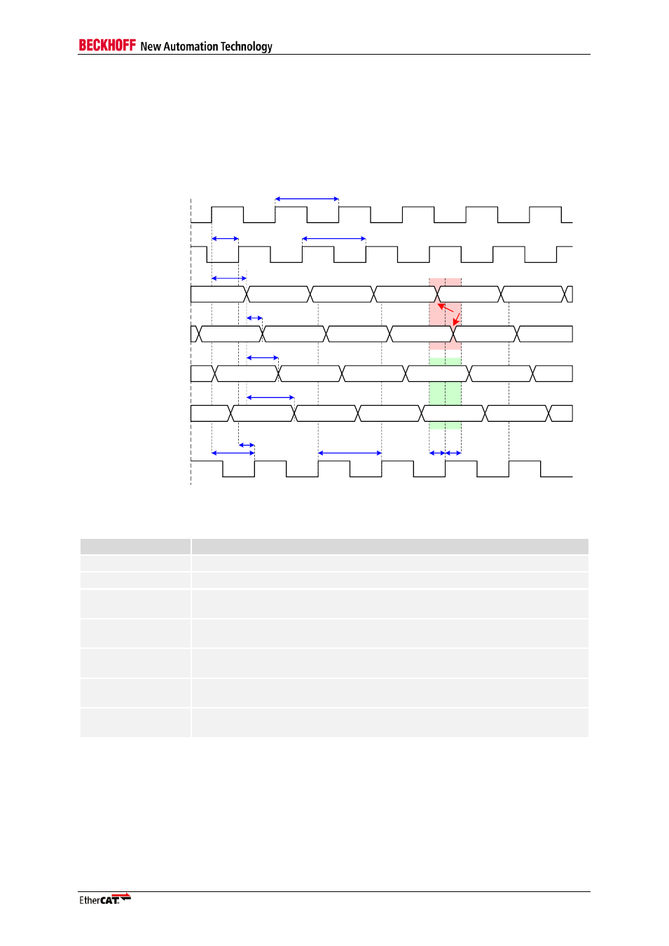
TX Shift Compensation
Since ET1100 and the Ethernet PHY share the same clock source, TX_CLK from the PHY has a fixed
phase relation to TX_ENA/TX_D[3:0] from the ET1100. Thus, TX_CLK is not connected and the delay
of a TX FIFO inside the ET1100 is saved. The phase shift between TX_CLK and TX_ENA/TX_D[3:0]
can be compensated by an appropriate value for TX Shift, which will delay TX_ENA/TX_D[3:0] by 0,
10, 20, or 30 ns.
OSC_IN
CLK25OUT1/2
TX_CLK
TX_ENA
TX_D[3:0]
t
Clk25Out1/2
TX_ENA
TX_D[3:0]
TX_ENA
TX_D[3:0]
TX_ENA
TX_D[3:0]
TX_ENA
TX_D[3:0]
TX_ENA
TX_D[3:0]
TX_ENA
TX_D[3:0]
TX_ENA
TX_D[3:0]
TX_ENA
TX_D[3:0]
TX_ENA
TX_D[3:0]
TX_ENA
TX_D[3:0]
TX_ENA
TX_D[3:0]
TX_ENA
TX_D[3:0]
TX_ENA
TX_D[3:0]
TX_ENA
TX_D[3:0]
TX_ENA
TX_D[3:0]
t
CLK25
t
PHY_TX_CLK_delay1/2
10 ns
20 ns
30 ns
t
TX_delay
t
PHY_TX_hold
t
PHY_TX_setup
Wrong: Setup/Hold Timing violated
Good: Setup/Hold Timing met
t
CLK25
t
CLK25
t
PHY_TX_CLK_delay_OSC
TX_ENA, TX_D[3:0]
TX_Shift[1:0]=00
TX_ENA, TX_D[3:0]
TX_Shift[1:0]=01
TX_ENA, TX_D[3:0]
TX_Shift[1:0]=10
TX_ENA, TX_D[3:0]
TX_Shift[1:0]=11
Figure 6: TX Shift Timing Diagram
Table 50: TX Shift Timing characteristics
Parameter
Comment
t
CLK25
25 MHz clock source period (OSC_IN, see f
CLK25
)
t
CLK25OUT1/2
CLK25OUT1/2 delay after OSC_IN (refer to AC characteristics)
t
TX_delay
TX_ENA/TX_D[3:0] delay after rising edge of OSC_IN (refer to AC
characteristics)
t
PHY_TX_CLK_delay1/2
Delay between PHY clock source CLK25OUT1/2 and TX_CLK output of the
PHY, PHY dependent.
t
PHY_TX_CLK_delay_OSC
Delay between PHY clock source OSC_IN and TX_CLK output of the PHY,
PHY dependent.
t
PHY_TX_setup
PHY setup requirement: TX_ENA/TX_D[3:0] with respect to TX_CLK. (PHY
dependent, IEEE802.3 limit is 15 ns)
t
PHY_TX_hold
PHY hold requirement: TX_ENA/TX_D[3:0] with respect to TX_CLK. (PHY
dependent, IEEE802.3 limit is 0 ns)
NOTE: TX Shift can be adjusted by displaying TX_CLK of a PHY and TX_ENA/TX_D[3:0] on an oscilloscope.
TX_ENA/TX_D is allowed to change between 0 ns and 25 ns after a rising edge of TX_CLK (according to
IEEE802.3
– check your PHY’s documentation, it may contain relaxed timing requirements). Configure TX Shift so
that TX_ENA/TX_D[3:0] change near the middle of this range. It is sufficient to check just one of the
TX_ENA/TX_D[3:0] signals, because they are generated nearly at the same time.