1 physical port signals, 2 mii interface, 1 clk25out1/2 signals – BECKHOFF ET1100 User Manual
Page 39: Physical port signals, Mii interface, Table 32: clk25out1/2 signal output
Pin Description
Slave Controller
– ET1100 Hardware Description
III-25
3.8.1
Physical Port Signals
3.8.2
MII Interface
LINK_MII(x)
Input signal provided by the PHY if a 100 Mbit/s (Full Duplex) link is established. LINK_MII(x) polarity
is configurable.
RX_CLK(x)
MII Receive Clock
RX_DV(x)
MII receive data valid.
RX_D(x)[3:0]
MII receive data.
RX_ERR(x)
MII receive error.
TX_ENA(x)
MII transmit enable output. Used as MII transmit enable input for controlling the Link/Activity LED if
port is in transparent mode (TRANS_MODE_ENA=1 and TRANS(x)=0).
TX_D(x)[3:0]
MII transmit data.
3.8.2.1
CLK25OUT1/2 Signals
The ET1100 has to provide the Ethernet PHYs with a 25 MHz clock signal (CLK25OUT) if a 25 MHz
crystal is used for clock generation. In case a 25 MHz oscillator is used, CLK25OUT is not necessary,
because Ethernet PHYs and ET1100 can share the oscillator output. Depending on the port
configuration and C25_ENA, CLK25OUT is available at different pins:
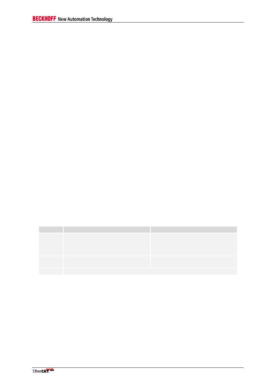
Table 32: CLK25OUT1/2 signal output
Conf.
C25_ENA=0
C25_ENA=1
0-2xMII
LINK_MII(2)/CLK25OUT1 provides
CLK25OUT
(PDI[31]/CLK25OUT2 also provides
CLK25OUT if 4 ports are used)
LINK_MII(2)/CLK25OUT1 and
PDI[31]/CLK25OUT2 provide
CLK25OUT
3xMII
CLK25OUT not available,
oscillator is mandatory
PDI[31]/CLK25OUT2 provides
CLK25OUT
4xMII
PDI[31]/CLK25OUT2 provides CLK25OUT
NOTE: Unused CLK25OUT pins should not be connected to reduce driver load.
The CLK25OUT pins provide a clock signal
– if configured – during external or ECAT reset, clock
output is only turned off during power-on reset.