7 10 baset/100 basetx connector pin assignments, Pin assignments – Artesyn MVME51005E SBC Installation and Use (July 2014) User Manual
Page 112
Pin Assignments
MVME51005E Single Board Computer Installation and Use (6806800A38D)
114
Note: Since the P2 adaptor card for the MVmE712M is a three (3) row connector, signals on
Rows Z and D are not routed to the MVME712M. Thus
(a) although the IPMC712 controller is capable of 16-bit (wide) SCSI operations only 8-bit
(narrow) transfers are supported through the MVME712M
(b) PMC I/O from site two (2) is not available through the MVME712M
(c) Please remember the caution stated on page 5-25 that a PMC located at site two (2) may
not connect to pins J24-2, 5, 8, 11, 14, 17, 20, 23 and 26.
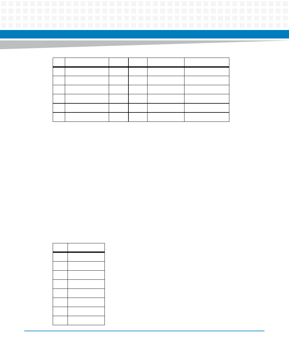
6.3.7
10 BaseT/100 BaseTx Connector Pin Assignments
The board’s dual 10 BaseT/100 BaseTx RJ45 connectors (J9 and J18) are located on the front
plate. The connections provide two LAN connections (LAN1-J18 and LAN2-J9). The pin
assignments for these connectors are as follows:
27
PMC2_41 (J24-41)
RTS4
VD28
TXD2
PMC2_40 (J24-40)
28
GND
TRXC4
VD29
RXD2
PMC2_42 (J24-42)
29
PMC2_44 (J24-44)
CTS4
VD30
RTS2
PMC2_43 (J24-43)
30
GND
DTR4
VD31
CTS2
PMC2_45 (J24-45)
31
PMC2_46 (J24-46)
DCD4
GND
DTR2
GND
32
GND
RTXC4
+5V
DCD2
VPC
Pin
Row Z
Row A
Row B
Row C
Row D
Pin
Assignment
1
TD+
2
TD-
3
RD+
4
AC Terminated
5
AC Terminated
6
RD-
7
AC Terminated
8
AC Terminated
- ARTM-9405 16x10GbE Installation and Use Guide (May 2014) (64 pages)
- ATCA 7370 / ATCA 7370-S Installation and Use (January 2015) (256 pages)
- ATCA 7370 / ATCA 7370-S Installation and Use (September 2014) (254 pages)
- ARTM-831X Installation and Use (June 2014) (346 pages)
- ATCA-7350 - Integrating with Workbench User Guide (September 2014) (34 pages)
- ATCA-7350 Installation and Use (September 2014) (208 pages)
- ATCA-7365-CE Installation and Use (May 2014) (306 pages)
- ATCA-7365-CE Installation and Use (Jan 2015) (300 pages)
- ATCA-7365-CE Installation and Use (May 2014) (294 pages)
- ATCA-7368 Installation and Use (June 2014) (222 pages)
- ATCA-7475 Installation and Use (October 2014) (284 pages)
- ATCA-7480 Installation and Use (April 2015) (330 pages)
- ATCA-8330 Installation and Use (April 2015) (236 pages)
- ATCA-8320 Installation and Use (May 2014) (456 pages)
- ATCA-9305 User's Manual (May 2014) (270 pages)
- ATCA-9405 Installation and Use (October 2014) (168 pages)
- ATCA-F120 Installation and Use (August 2014) (122 pages)
- ATCA-F140 Installation and Use (September 2014) (138 pages)
- ATCA-MF106 Installation and Use (September 2014) (86 pages)
- Centellis-4440/AXP1440 Installation and Use (September 2014) (208 pages)
- Centellis 4410 (AXP-1410) Installation and Use (July 2014) (202 pages)
- Centellis 2100 Release 3.0 Installation and Use (March 2015) (192 pages)
- Centellis 2100 Release 3.0 Installation and Use (March 2015) (176 pages)
- Centellis 2000 User Card-10GE Installation and Use (May 2014) (54 pages)
- Centellis 2000 User Card-10GE with Telco Alarm Installation and Use (May 2014) (60 pages)
- COMX-CAR-210 Installation and Use (August 2014) (76 pages)
- COMX-P1022 Installation and Use (July 2014) (84 pages)
- COMX-P2020 Installation and Use (February 2015) (100 pages)
- COMX-CORE Series Installation and Use (August 2014) (128 pages)
- COMX-P2020 Installation and Use (July 2014) (100 pages)
- COMX-P4080-2G-ENP2 Installation and Use (August 2014) (70 pages)
- COMX-P4080 Installation and Use (August 2014) (126 pages)
- COMX-P40x0 ENP2 Installation and Use (August 2014) (130 pages)
- COMX-P40x0 ENP2 Installation and Use (January 2015) (140 pages)
- iVPX7225 RTM Installation and Use (April 2015) (56 pages)
- MITX-430/MITX-440-DVI-2E Installation and Use (August 2014) (118 pages)
- CPCI-6200 Installation and Use (May 2015) (234 pages)
- SCP-MITX-CORE-820-SM Installation and Use (August 2014) (132 pages)
- iVPX7225 Installation and Use (April 2015) (168 pages)
- MVME2502 Installation and Use (August 2014) (150 pages)
- MVME2502 Installation and Use (December 2014) (166 pages)
- MVME2500 VxWorks 6.8 AMP User Guide (August 2014) (40 pages)
- MVME2500 VxWorks 6.8 User Guide (April 2014) (44 pages)
- MVME3100 Single Board Computer Installation and Use (June 2014) (156 pages)
- MVME4100 Single Board Computer Installation and Use (June 2014) (136 pages)