3 physical interconnect devices, 4 amc bay, 5 rear transition module – Artesyn ATCA-F125 Installation and Use Guide (April 2014) User Manual
Page 96: Figure 4-15, Amc enable logic
Functional Description
ATCA-F125 (6873M Artwork) Installation and Use (6806800J94J)
96
4.12.3 Physical Interconnect Devices
Broadcom PHYs uses a hardware reset pin PHY_RST_L, which resets all internal nodes to a
known state. Mode pins are latched during hardware reset being deasserted. All PHYs are reset
by the PHY_RST_L signal except for the BCM8747 which is reset by QUAD_PHY_RST_L.
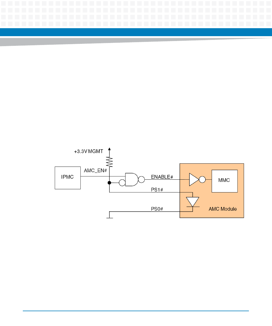
4.12.4 AMC Bay
The IPMC on the ATCA-F125 is responsible for resetting the AMC bay. It initiates a reset cycle
after an AMC module is plugged in or if the payload power of the carrier board is in a power
cycle. The IPMC drives the ENABLE# signal active low as an input to the AMC module.
Broadcom BCM5709S Ethernet controller is reset in parallel to AMC by using the
MACPHY_RST_L signal generated from the power control CPLD.
4.12.5 Rear Transition Module
The ARTM-F125 does not have an MMC. During normal operation the ARTM-F125 and the
ATCA-F125 front board are treated as one reset domain using the RTM_RST_L signal from the
FPGA.
Figure 4-15 AMC Enable Logic