Table 3-4, Service processor usb connector (j10), Table 3-5 – Artesyn ATCA-F125 Installation and Use Guide (April 2014) User Manual
Page 50: Sfp+ connectors pin assignment (j4-j7), Controls, leds, and connectors
Controls, LEDs, and Connectors
ATCA-F125 (6873M Artwork) Installation and Use (6806800J94J)
50
4
GND
5
GND
6
RX
7
Not used
8
CTS
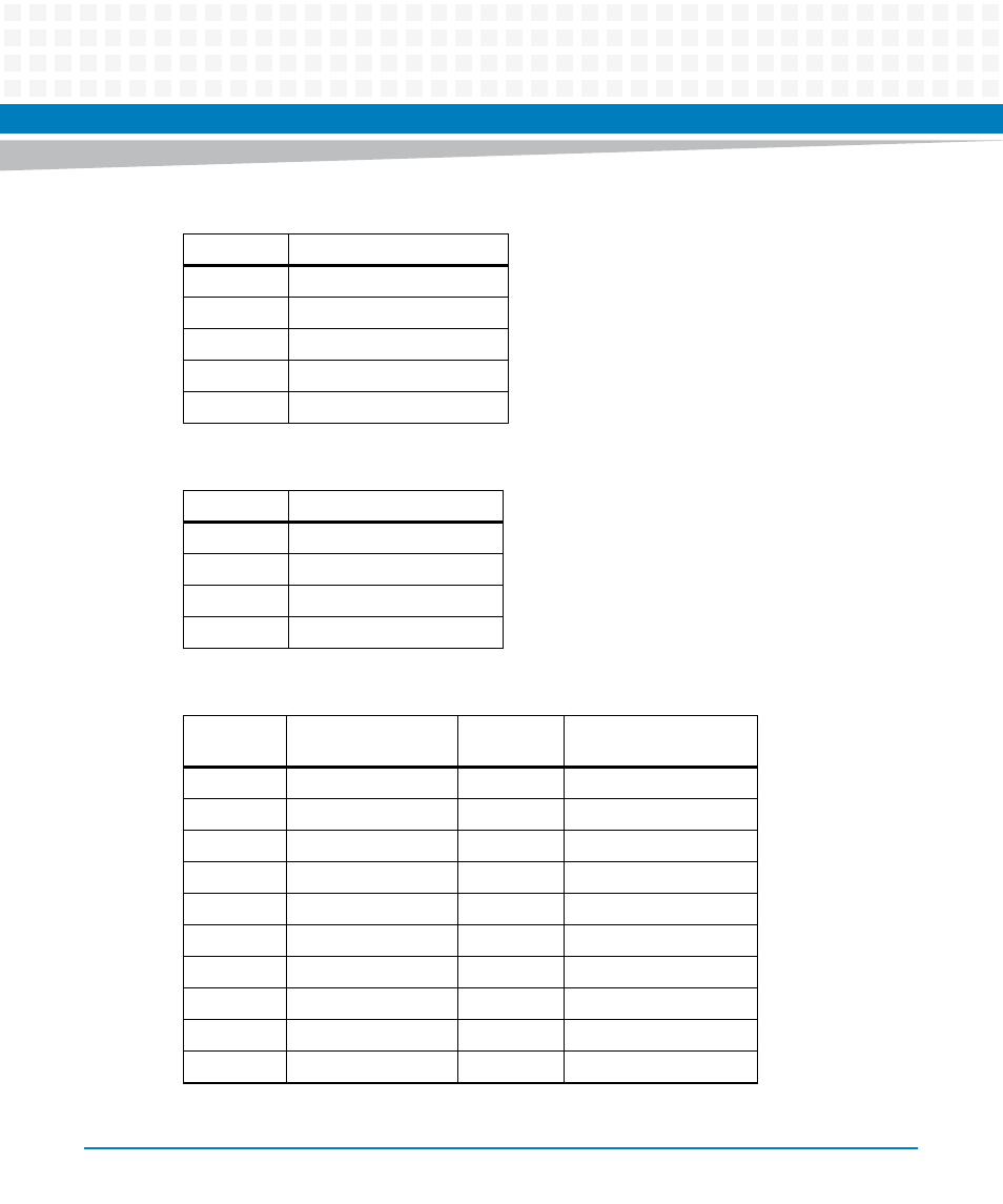
Table 3-4 Service Processor USB Connector (J10)
USB Pin
Function
1
+0.5 V
2
DATA_N
3
DATA_P
4
GND
Table 3-5 SFP+ Connectors Pin Assignment (J4-J7)
Contact
Number
Function
Contact
Number
Function
1
GND
11
GND
2
TX_FAULT
12
RX-
3
TX_DISABLE
13
RX+
4
I2C_SDA
14
GND
5
12C_SCL
15
VCCr (+3.3 V)
6
MOD_ABS
16
VCCr (+3.3 V)
7
RATE_SEL
1
17
GND
8
LOS
18
TX+
9
GND
19
TX-
10
GND
20
GND
1. Configured with a pull-up to allow high speed connection
Table 3-3 Service Processor Serial RS232 RJ45 Connector (J1) (continued)
RJ45 Pin
Function (RS232)