Controls, leds, and connectors, 1 overview, 2 blade layout – Artesyn ATCA-F125 Installation and Use Guide (April 2014) User Manual
Page 47: 3 faceplate leds, 1 overview 3.2 blade layout 3.3 faceplate leds, Table 3-1, Faceplate leds, Figure 3-1, Atca-f125 face plate, Chapter 3
Chapter 3
ATCA-F125 (6873M Artwork) Installation and Use (6806800J94J)
47
Controls, LEDs, and Connectors
3.1
Overview
3.2
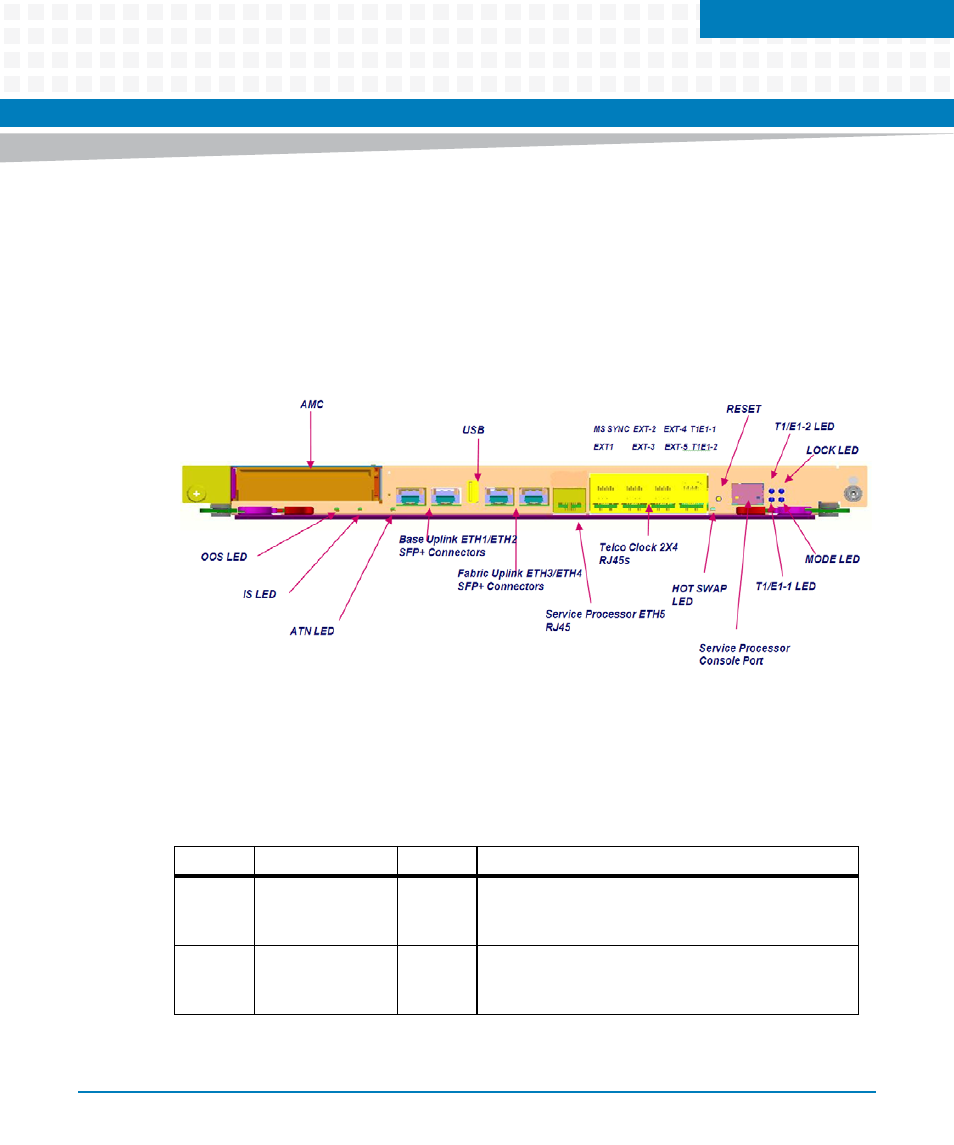
Blade Layout
The following figure shows the front panel face plate design.
3.3
Faceplate LEDs
This section describes the details of the ATCA-F125 faceplate LEDs.
Figure 3-1
ATCA-F125 Face Plate
Table 3-1 Faceplate LEDs
Label
LED
Color
Function
OOS
Out of Service
Red
This LED is enabled by the IPMC upon initially entering
the M4 state. Once the HPM Agent starts up, this LED
is disabled.
IS
In Service
Green
This LED is enabled by HPM Agent upon initialization.
This indicates that the payload software is up and
running.