4 reset switch, 5 faceplate connectors, 4 reset switch 3.5 faceplate connectors – Artesyn ATCA-F125 Installation and Use Guide (April 2014) User Manual
Page 49: Table 3-2, Table 3-3, Service processor serial rs232 rj45 connector (j1), Controls, leds, and connectors
Controls, LEDs, and Connectors
ATCA-F125 (6873M Artwork) Installation and Use (6806800J94J)
49
3.4
Reset Switch
The front panel has a recessed reset switch. A small pointed object must be inserted through
the hole in the front panel to activate the reset switch. Activating this switch will reset the
service processor and all of the ethernet switches. It will not reset the IPMC or the AMC.
3.5
Faceplate Connectors
The following tables provide the pinout for the face plate connectors.
Red
Blinking - Initializing
Table 3-1 Faceplate LEDs (continued)
Label
LED
Color
Function
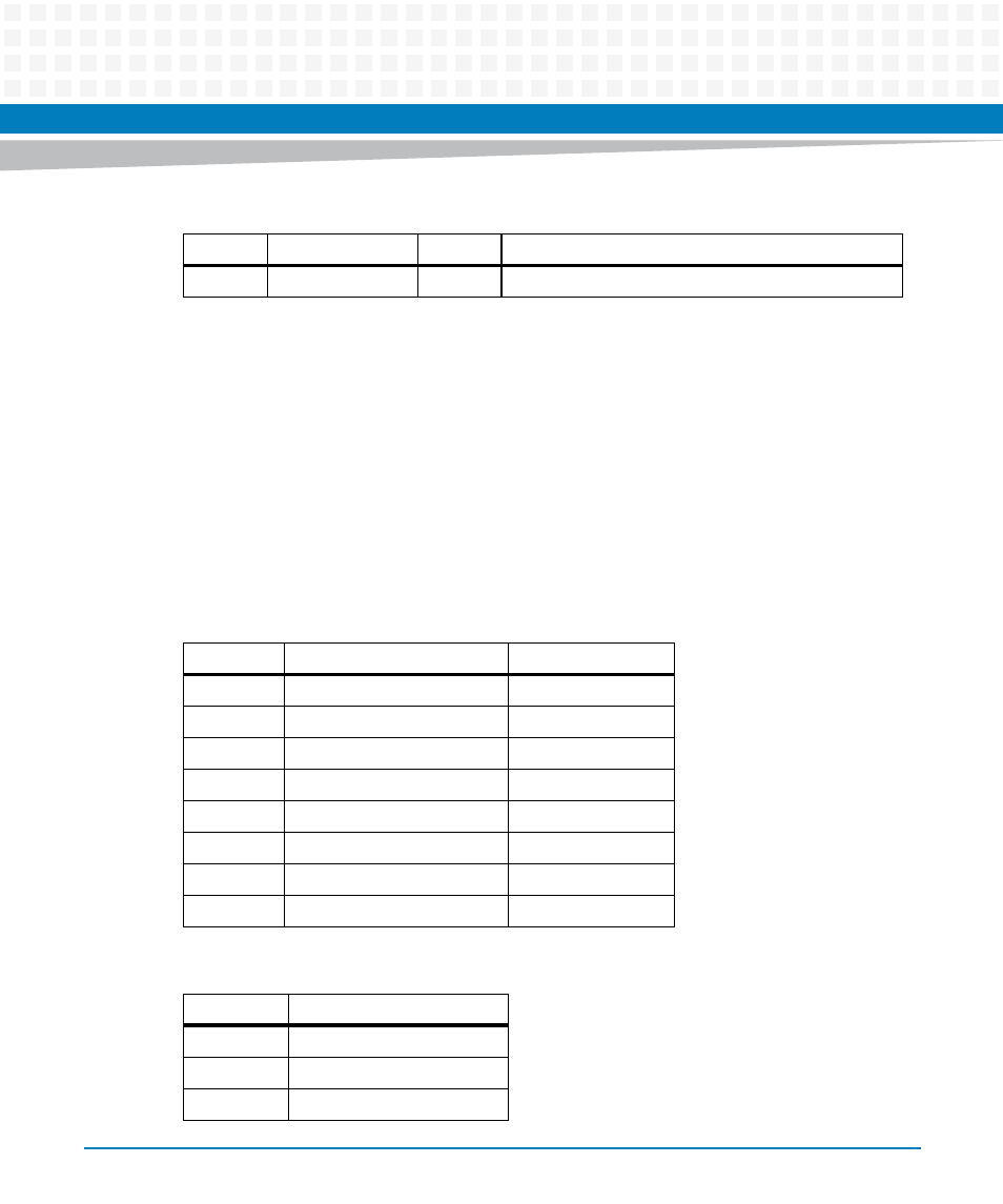
Table 3-2 Service Processor Ethernet RJ45 Connector Pin Assignment (J9)
RJ45 Pin
10Base-T or 100Base-TX
1000Base-T
1
ETH_TX+
ETH_DA+
2
ETH_TX-
ETH_DA-
3
ETH_RX+
ETH_DB+
4
ETH_DC+
5
ETH_DC-
6
ETH_RX-
ETH_DB-
7
ETH_DD+
8
ETH_DD-
Table 3-3 Service Processor Serial RS232 RJ45 Connector (J1)
RJ45 Pin
Function (RS232)
1
RTS
2
Not used
3
TX