6 backplane connectors, 1 zone 1, Table 3-9 – Artesyn ATCA-F125 Installation and Use Guide (April 2014) User Manual
Page 52: Zone 1 connector p1 pin assignment, Controls, leds, and connectors
Controls, LEDs, and Connectors
ATCA-F125 (6873M Artwork) Installation and Use (6806800J94J)
52
3.6
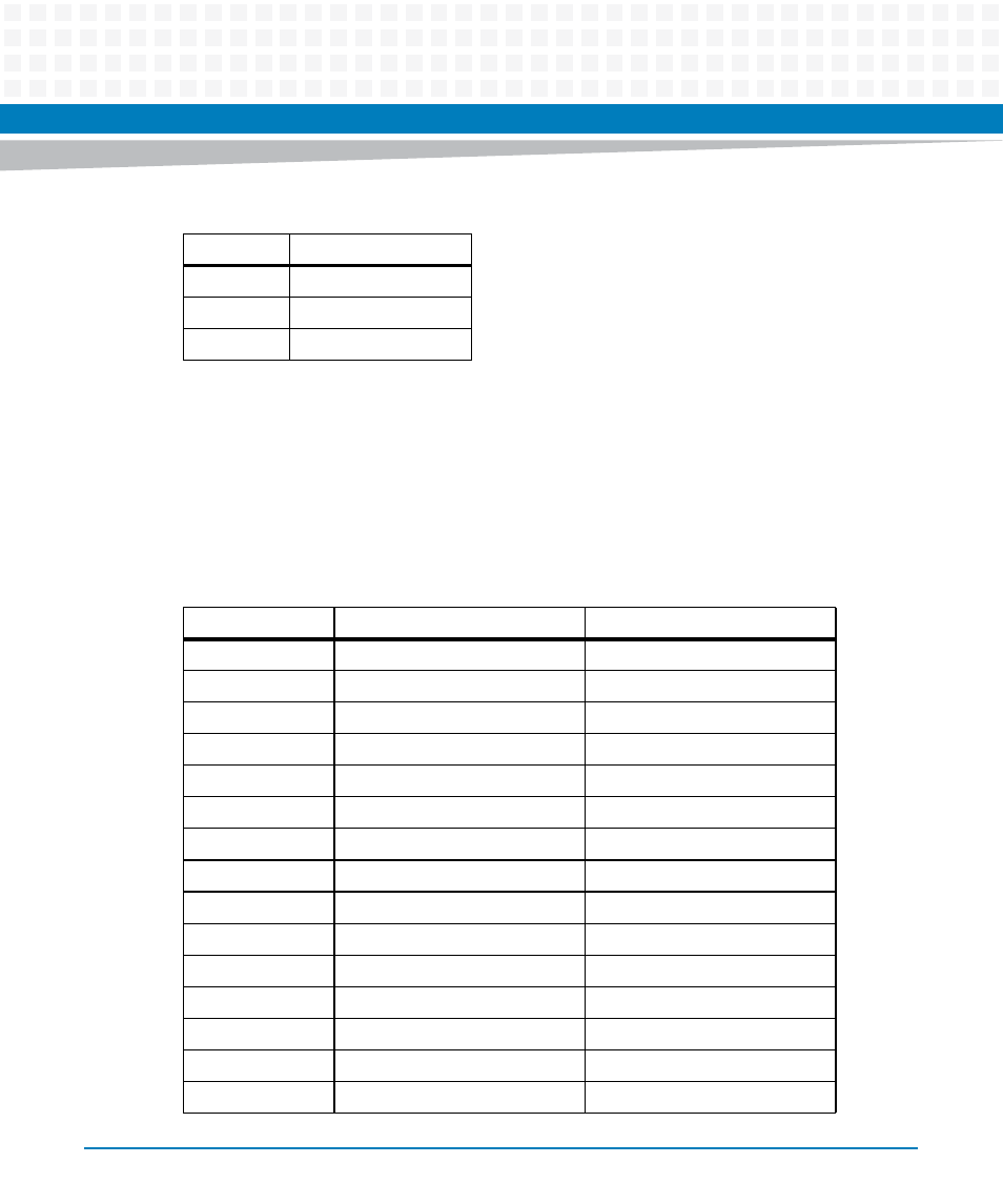
Backplane Connectors
3.6.1
Zone 1
The following table shows the pinout assignment for the Zone 1 ATCA power connector.
6
Port 2 -
7
Shield
8
Shield
Table 3-8 T1/E1 Port Connectors (J12-L4 and J12-U4)
RJ45 Pin
Function
Table 3-9 Zone 1 Connector P1 Pin Assignment
Contact Number
Destination
Description
1 - 4
Reserved
Reserved
5
IPMC Port 2 bit 0
Hardware Address Bit 0
6
IPMC Port 2 bit 1
Hardware Address Bit 1
7
IPMC Port 2 bit 2
Hardware Address Bit 2
8
IPMC Port 2 bit 3
Hardware Address Bit 3
9
IPMC Port 2 bit 4
Hardware Address Bit 4
10
IPMC Port 2 bit 5
Hardware Address Bit 5
11
IPMC Port 2 bit 6
Hardware Address Bit 6
12
IPMC Port 2 bit 7
Hardware Address Bit 7
13
IPMC Port C bit 0
IPMB Clock Port A
14
IPMC Port C bit 1
IPMB Data Port A
15
IPMC Port C bit 2
IPMB Clock Port B
16
IPMC Port C bit 3
IPMB Data Port A
17 - 24
Not used
Not used
25
Shelf Ground
Shelf Ground