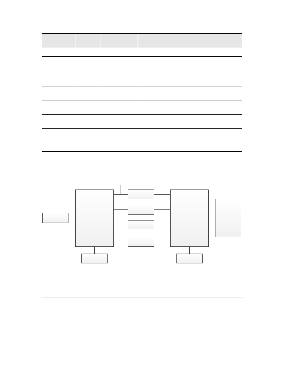
Configuring a series 5000 half-router, Ee configuring a series 5000 half-router, Figure 39 – Echelon LonWorks Router User Manual
Page 89
I2C: serial data
SPI: slave select 1 (active low)
(from internal voltage regulator)
SPI master input, slave output (MISO)
SPI master output, slave input (MOSI)
Clock Pins (XIN and XOUT) show information about the Series 5000
router clock requirements and how to use the Series 5000 router XOUT
pin to drive an external clock.
Series 5000 Router
(Router 5000 or FT 5000
Router)
B Side
Series 3100 Router
A Side
Reset Circuitry
Service Circuitry
Clock Circuitry
Clock Circuitry
LDO Regulator
IO Lines
Input
Output
+ 3.3 V
Transceiver for
Router 5000
Or
FT-X3
Communications
Transformer for
FT 5000 Router
Transceiver
+ 5 V
Figure 39. Basic Connections for Series 3100 and Series 5000 Half-Routers
See the FT 3120 / FT 3150 Smart Transceiver Databook or the PL 3120/PL
3150/PL 3170 Power Line Smart Transceiver Data Book for more information
about Series 3100 chips.
Configuring a Series 5000 Half-Router
Before programming, a Router 5000 uses its default communications parameters,
which define a simplified single-ended mode 78 kbps channel. Like the Router
5000, an FT Router 5000’s default communications parameters define a
simplified single-ended mode 78 kbps channel – a TP/FT-10 channel. For the
L
ON
W
ORKS
Router User’s Guide
79