Power supply decoupling and filtering, Low voltage protection – Echelon LonWorks Router User Manual
Page 56
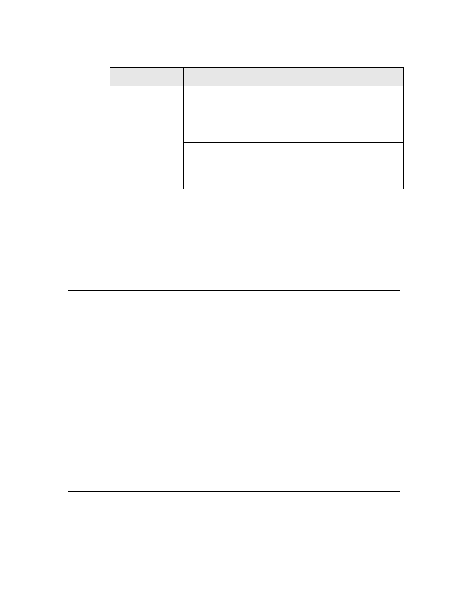
Table 12. Series 5000 Router Current Requirements
Active
SysClk
Typical
Maximum
Receive Current
5 MHz
9 mA
15 mA
10 MHz
9 mA
15 mA
20 MHz
15 mA
23 mA
40 MHz
23 mA
33 mA
Transmit Current 5 – 40 MHz
Receive Current
+ 15 mA
Receive Current
+ 18 mA
The Series 5000 router chip requires a 3.3 V nominal power supply (3.0 V to 3.6 V
range). The current requirements assume no load on digital I/O pins, and that
the I/O lines are not switching. In addition, the current consumption in transmit
mode represents a peak value rather than a continuous usage value because a
Series 5000 router does not typically transmit data continuously.
Note that the stated current requirements do not include the requirements for
performing reads or writes to the external memory (the two-wire serial
EEPROM), which typically add 1 to 2 mA. When not in use, the EEPROM
typically requires only 2 μA.
Power Supply Decoupling and Filtering
The design for a L
ON
W
ORKS
router power supply must consider filtering and
decoupling requirements of the router. The power supply filter must prevent
noise generated by the router from conducting onto external wires, and in the
case of DC-DC switching power supplies, must prevent noise generated by the
supply from interfering with router operation. Switching power supply designs
must also consider the effects of radiated EMI.
An RTR-10 router or a Series 5000 half-router each requires a clean power supply
to prevent RF noise from conducting onto the network through active drive
circuits. Power supply noise near the network transmission frequency could
degrade network performance.
The RTR-10 router includes 2.2 μF and 0.1 μF power supply bypass capacitors
close to pins 10 and 31. In general, high-frequency decoupling capacitors valued
at 0. 1μF or 0.01 μF placed near pins 10 and 31 on the motherboard are
necessary to reduce EMI.
See the Series 5000 Chip Data Book for information about power-supply
decoupling and filtering for Series 5000 chips, including the Router 5000 and FT
Router 5000.
Low Voltage Protection
For a RTR-10 design, it is necessary to include a low voltage protection circuit on
the router motherboard to drive the RESET~ line of the RTR-10 router. See
Section 9.4 of the Neuron Chip Data Book. Failure to include such protection
may cause data corruption to configuration data maintained in EEPROM on the
46
LONWORKS Router Electrical Interfaces