Echelon LonWorks Router User Manual
Page 50
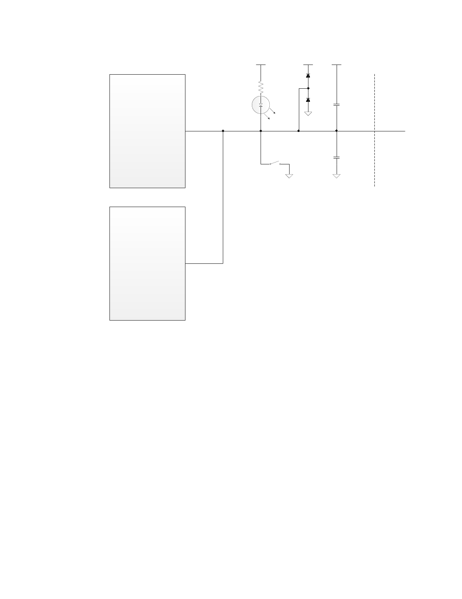
Series 5000 Router
(Router 5000 or FT Router
5000)
A Side
RST~
+ 5 V
+ 5 V
100 pF
100 pF
+ 5 V
To other
devices
Series 3100 Router
B Side
RESET~
Reset
Figure 17. Reset Circuit – Series 5000 Router with Series 3100 Router
Typical applications do not require debounce conditioning of a momentary
pushbutton attached to the RST~ pin. The software response time associated
with this input is long enough to effectively provide a software debounce for
switches with a contact bounce settling time as long as 20 milliseconds. The
RST~ signal must be driven low by a low voltage protection circuit on the router
motherboard as described in Low Voltage Protection.
See the Series 5000 Chip Data Book for more information about the RST~ pin for
a Series 5000 chip, including the Router 5000 and FT Router 5000.
SVC~
The SVC~ pin alternates between input and open-drain output at a 76 Hz rate
with a 50% duty cycle. When it is an output, it can sink up to 8 mA for use in
driving an LED. When it is used exclusively as an input, it uses an optional
external pull-up to bring the input to an inactive-high state.
Under control of the Neuron firmware, this pin is used during configuration,
installation, and maintenance of the Series 5000 router device. The firmware
flashes the LED at a 1/2 Hz rate when the Series 5000 router chip has not been
configured with network address information. Grounding the SVC~ pin causes
the Series 5000 router to transmit a network management message containing
40
LONWORKS Router Electrical Interfaces