Overview, Electrical interface, Rtr-10 electrical interface – Echelon LonWorks Router User Manual
Page 32
Overview
This chapter describes the electrical interface and power requirements for a
L
ON
W
ORKS
router.
Electrical Interface
The following sections describe the electrical interface for a L
ON
W
ORKS
router,
including detailed descriptions of each of the RTR-10, Router 5000, and FT
Router 5000 pins.
RTR-10 Electrical Interface
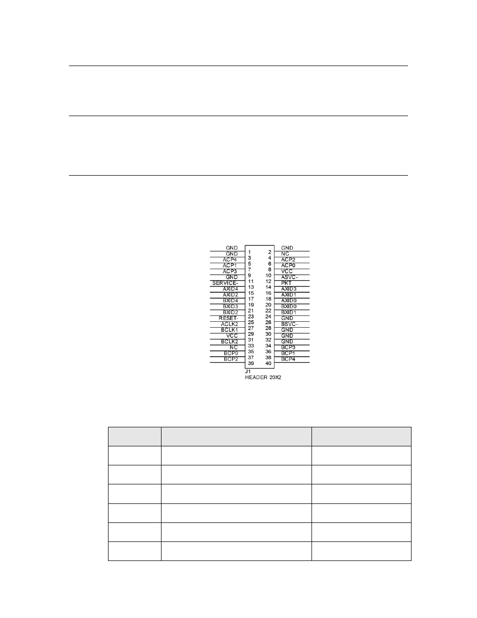
Figure 9 shows a schematic view of a connector for the RTR-10 Router Core
Module, and Table 6 shows the pinout of the RTR-10 Router Core Module. See
the Neuron Chip Data Book for more information about the use of the Neuron
Chip communications port pins.
Figure 9. RTR-10 Header Pinout
Table 6. RTR-10 Pinout
Pin Name
Pin Description
Pin Number
ACLK2
A-side output clock
27
ACP0
A-side network communication port 0
8
ACP1
A-side network communication port 1
7
ACP2
A-side network communication port 2
6
ACP3
A-side network communication port 3
9
ACP4
A-side network communication port 4
5
22
LONWORKS Router Electrical Interfaces