Connecting power – Echelon LonWorks Router User Manual
Page 105
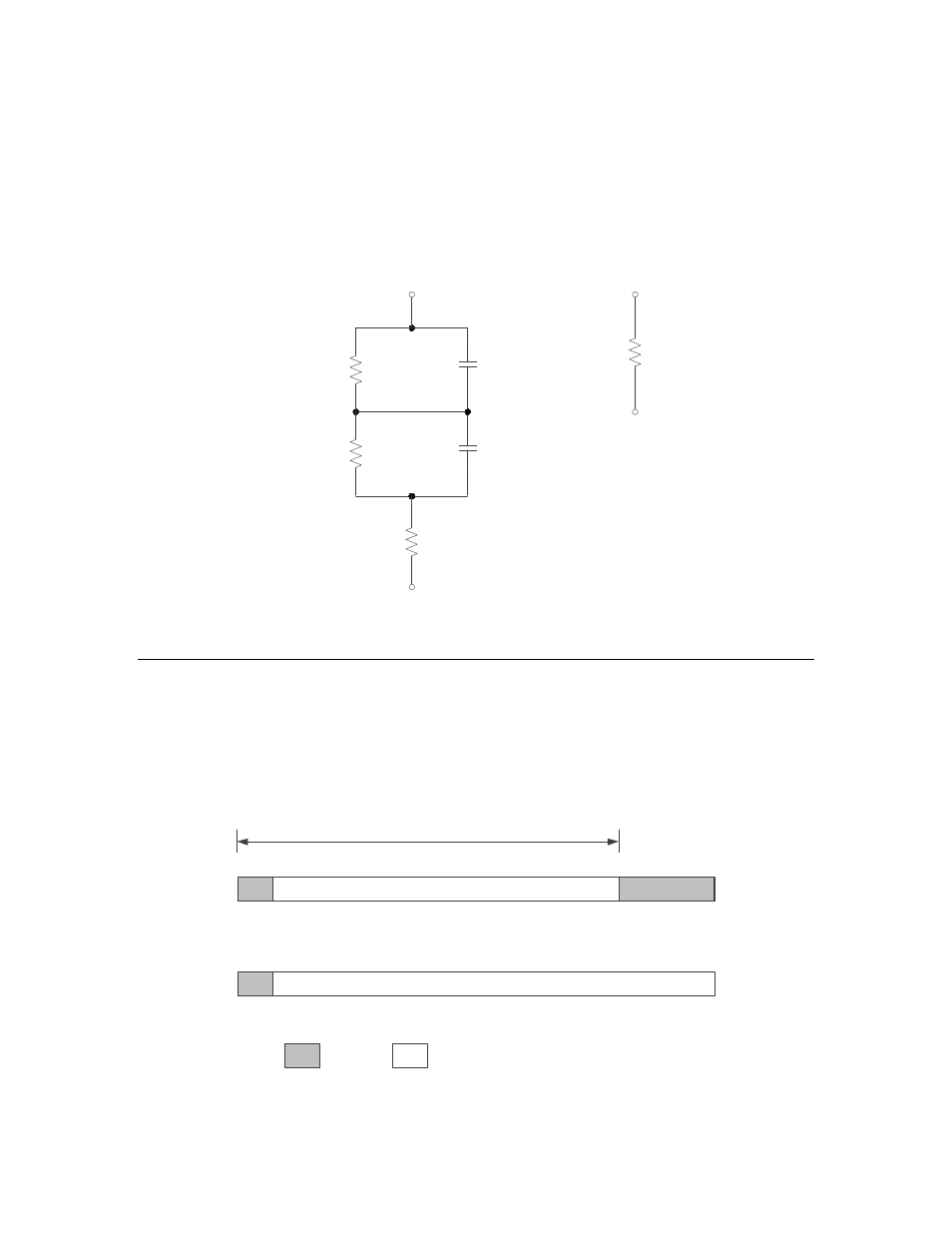
Proper electrical termination is essential for each twisted-pair channel. Failure
to terminate the network can degrade performance, and in some cases, eliminate
a device’s ability to communicate with other devices. For TP/XF and TP/RS485
channels, use the terminator circuits shown in Figure 44. You can also use the
terminators provided with the NodeBuilder FX Development Tool.
0.15 µF
10%
59 Ω
1%
0.33 µF
10%
340 Ω
1%
102 Ω
1%
120 Ω
5%
TP/XF-78,
TP/XF-1250, or
TP/RS485
Alternate for
TP/RS485 Only
Figure 44. Network Termination Circuits for TP/XF and TP/RS485
Networks
Connecting Power
After the router is physically attached to the desired channels, power must be
supplied.
When power is connected to a router, the Service LED for each side changes state
as described in Figure 45. After a router is powered and configured, the Service
LEDs stay off, unless the service request button is pressed.
2 seconds * (10/Input Clock)
Service LED Timing
for Unconfigured
Routers
Service LED Timing
for Configured
Routers
ON
OFF
Figure 45. Router Service LED Timing
L
ON
W
ORKS
Router User’s Guide
95