Io[11 – Echelon LonWorks Router User Manual
Page 46
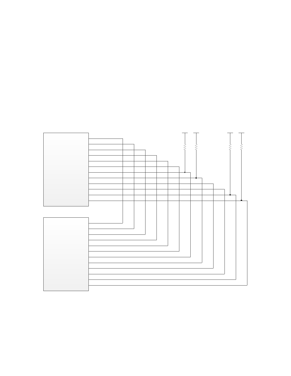
IO[11..0]
These digital I/O pins provide the communications between the A side and B side
of a Series 5000 router device. Connect the IO pins for one router side to the
corresponding IO pin on the other router side, as shown in Figure 15.
Note that you must provide 10 kΩ pull-up resistors for the IO6, IO7, and IO10
pins. During power-up, the router half performs signal arbitration tests that
require the pull-ups on IO6 and IO7. The IO10 pull-up is for the handshake
signal between router halves. The IO11 pin is not used for either router half, but
it should be pulled up with a 10 kΩ pull-up resistor.
If your router uses a Series 3100 half-router for one of its sides, and the Series
3100 Smart Transceiver does not have an IO11 pin, tie the Series 5000 half-
router’s IO11 pin high with a 10 kΩ pull-up resistor.
Series 5000 Router
(Router 5000 or FT Router
5000)
A Side
IO5
IO0
IO1
IO2
IO3
IO4
IO6
IO7
IO8
IO9
IO10
IO11
Series 5000 Router
(Router 5000 or FT Router
5000)
B Side
IO5
IO0
IO1
IO2
IO3
IO4
IO6
IO7
IO8
IO9
IO10
IO11
10k
3.3 V
10k
10k
3.3 V
3.3 V
10k
3.3 V
Figure 15. Digital IO Pin Connections
Important: When routing the IO[11..0] signals between the two router halves
of your Series 5000 router device, keep the traces as short as possible.
See the Series 5000 Chip Data Book for more information about the digital I/O
pins for a Series 5000 chip, including the Router 5000 and FT Router 5000.
36
LONWORKS Router Electrical Interfaces