Series 5000 router mechanical description, D figure 25 – Echelon LonWorks Router User Manual
Page 62
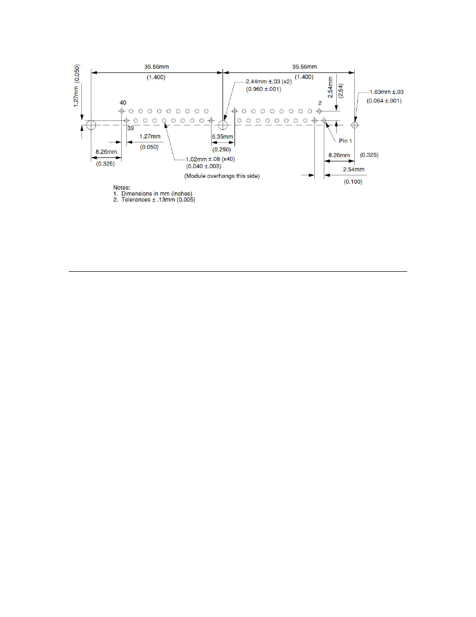
Figure 25. RTR-10 Recommended PCB Hole Pattern (Component Side, Horizontal
Mounting)
Decisions about component placement on the motherboard must consider
electromagnetic interference (EMI) and electrostatic discharge (ESD) issues; see
Chapter 5, LONWORKS Router Design Issues.
Series 5000 Router Mechanical Description
The mechanical description of the Series 5000 router chip is similar to the
mechanical description of general Series 5000 chips, as described in the Series
5000 Chip Data Book and the data sheet for the Neuron 5000 Processor or FT
5000 Smart Transceiver.
Figure 26 shows the mechanical specifications for a Series 5000 router chip.
52
LONWORKS Router Mechanical Interfaces