Differential driver circuit, Figure 30, Router user’s guide 61 – Echelon LonWorks Router User Manual
Page 71
CP2
CP1
CP4
CP3
CP0
DATA_B
DATA_A
CP3
CP2
GND
VDD5
CP0
CP1
2
5
4
3
9
7
6
1
37 TXEN
34 TX
39
38
32 RX
Router 5000
TPT/XF-1250
+5 V
VDD3V3
+3.3 V
8
8
CT
NET1
NET2
+3.3 V
Differential Driver
Circuit
Comparator
Circuit
10k
+3.3 V
0.1 µF
+5 V
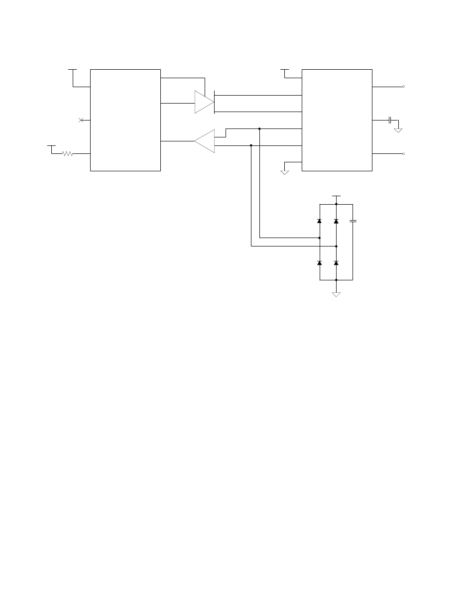
Figure 30. Connecting a Router 5000 to a TP/XF-1250 Transceiver
In the figure, the pullup resistor for the Router 5000’s CP4 pin is optional, but
helps prevent contention on the CP4 pin if the router is incorrectly configured to
operate in special-purpose mode (for which the CP4 pin is an output). The diode
clamps for the TPT/XF-1250 transceiver’s CP0 and CP1 signals are high-speed
switching diodes, such as Fairchild Semiconductor
®
1N4148 small-signal diodes.
The value of the capacitor on the TPT/XF-1250 transceiver’s transformer center
tap (CT) pin depends on the device’s PCB layout and EMI characteristics. A
typical value is 100 pF rated for 1000 V.
See the LonWorks TPT Twisted Pair Transceiver Module User's Guide for
information about the TPT/XF-1250 Transceiver.
Differential Driver Circuit
Figure 31 shows a differential driver circuit for connecting a Router 5000 to a
TPT/XF-1250 transceiver. The differential driver circuit buffers the Router
5000’s transmit (CP1) signal and transmit enable (CP2) signal to generate the
TPT/XF-1250 transceiver’s differential transmit signals (CP2 and CP3).
The heart of the differential driver circuit is a pair of 4-bit buffers/drivers in a
single 74HCT240 octal inverting buffer/line driver (such as the Texas
Instruments™ SN74HCT240 Octal Buffer and Line Driver with 3-State
Outputs).
L
ON
W
ORKS
Router User’s Guide
61