Echelon LonWorks Router User Manual
Page 17
Channel Type Transceiver for Half Router
Notes
Link-power
Echelon LPT-11 Link Power
Transceiver (Model 50040)
Add linear regulator and TX buffer
circuit.
Echelon provides special licensing for other transceiver types, such as a Power
Line Smart Transceiver; contact Echelon Support for additional information.
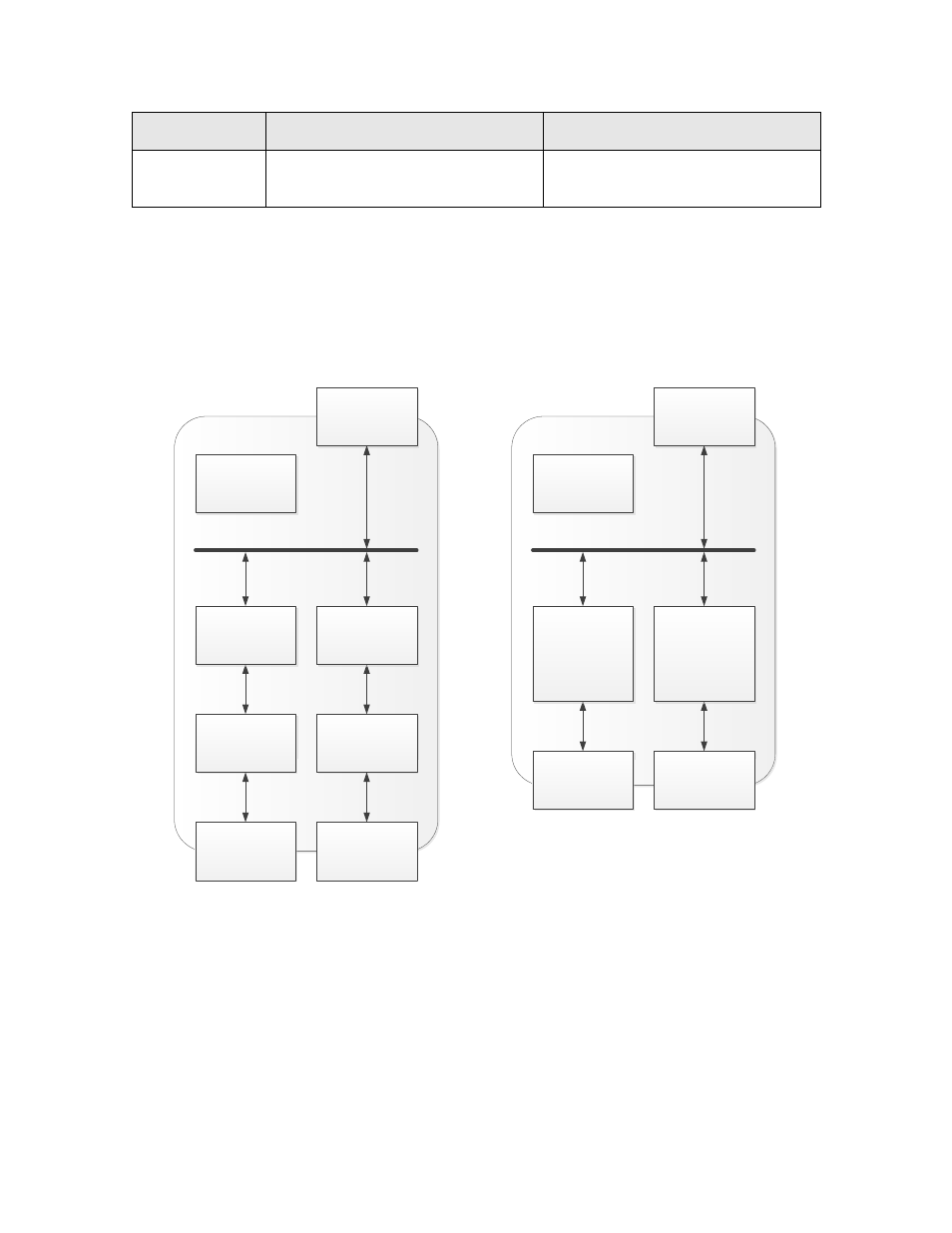
A complete router using the Router 5000 consists of two Router 5000 half routers,
two transceivers, and a motherboard to connect the two half routers. A complete
router using the FT Router 5000 consists of two FT Router 5000 half routers
(each with its own FT-X3 Communications Transformer), and a motherboard to
connect the two half routers. Figure 3 shows block diagrams of both types of
Series 5000 based routers.
Side A
Transceiver
Side B
Transceiver
Side A
Network
Connector
Side B
Network
Connector
Power Supply
Service
Buttons and
LEDs
Router 5000
Half Router
Router 5000
Half Router
Side A
Network
Connector
Side B
Network
Connector
Power Supply
Service
Buttons and
LEDs
FT Router
5000
(with FT-X3)
Half Router
FT Router
5000
(with FT-X3)
Half Router
LonWorks Router Based on the
Router 5000
LonWorks Router Based on the
FT Router 5000
Figure 3. Block Diagrams of L
ON
W
ORKS
Routers Based on a Series 5000 Router Chip
In the left side of the figure, two Router 5000 half routers and two transceiver
modules, one to handle each of two channels connected by the router, can be
mounted on a motherboard, along with a single power supply and two network
connectors. This sub-assembly constitutes a L
ON
W
ORKS
router. In the right side
of the figure, two FT Router 5000 half routers, one to handle each of two channels
connected by the router, can be mounted on a motherboard, along with a single
power supply and two network connectors. This sub-assembly constitutes a
L
ON
W
ORKS
Router User’s Guide
7