Ft router 5000 pinout – Echelon LonWorks Router User Manual
Page 39
Name
Pin
Number Type
Description
RST~
28
Digital I/O
Reset (active low)
VIN3V3
29
Power
3.3 V Power Input
VDD3V3
30
Power
3.3 V Power
AVDD3V3
31
Power
3.3 V Power
CP0
32
Comm
CP0: Receive serial data
AGND
33
Ground
Ground
CP1
34
Comm
CP1: Transmit serial data
NC
35
N/A
Do Not Connect
GND
36
Ground
Ground
CP2
37
Comm
CP2: External transceiver enable output
CP3
38
Comm
CP3: Do Not Connect
CP4
39
Comm
CP4: Collision detect input
CS0~
40
Digital I/O for
Memory
SPI slave select 0 (active low)
VDD3V3
41
Power
3.3 V Power
VDD3V3
42
Power
3.3 V Power
SDA_CS1~
43
Digital I/O for
Memory
I
2
C: serial data
SPI: slave select 1 (active low)
VDD1V8
44
Power
1.8 V Power Input
(from internal voltage regulator)
SCL
45
Digital I/O for
Memory
I
2
C serial clock
MISO
46
Digital I/O for
Memory
SPI master input, slave output (MISO)
SCK
47
Digital I/O for
Memory
SPI serial clock
MOSI
48
Digital I/O for
Memory
SPI master output, slave input (MOSI)
PAD
49
Ground Pad
Ground
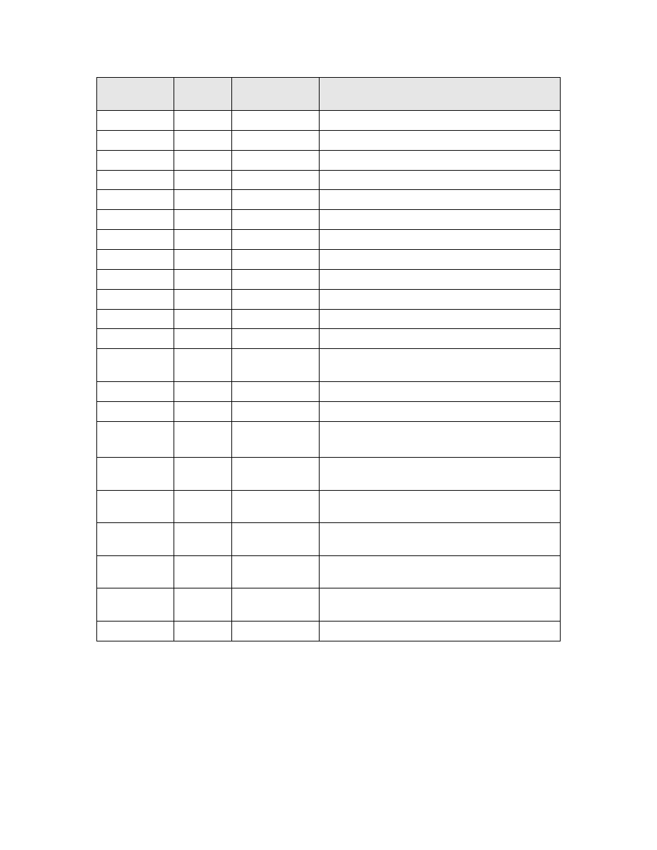
FT Router 5000 Pinout
Figure 12 shows the pinout for the FT Router 5000 chip. The central rectangle
in the figure represents the bottom pad (pin 49), which must be connected to
ground.
L
ON
W
ORKS
Router User’s Guide
29