Unit setup, Vehicle setup, Tilt gyro module setup – TeeJet Matrix 840G User Manual User Manual
Page 54: Fieldpilot setup, Commandes générales, System setup, Boompilot/single boom setup
www.teejet.com
88
●
98-05141 R2
89
●
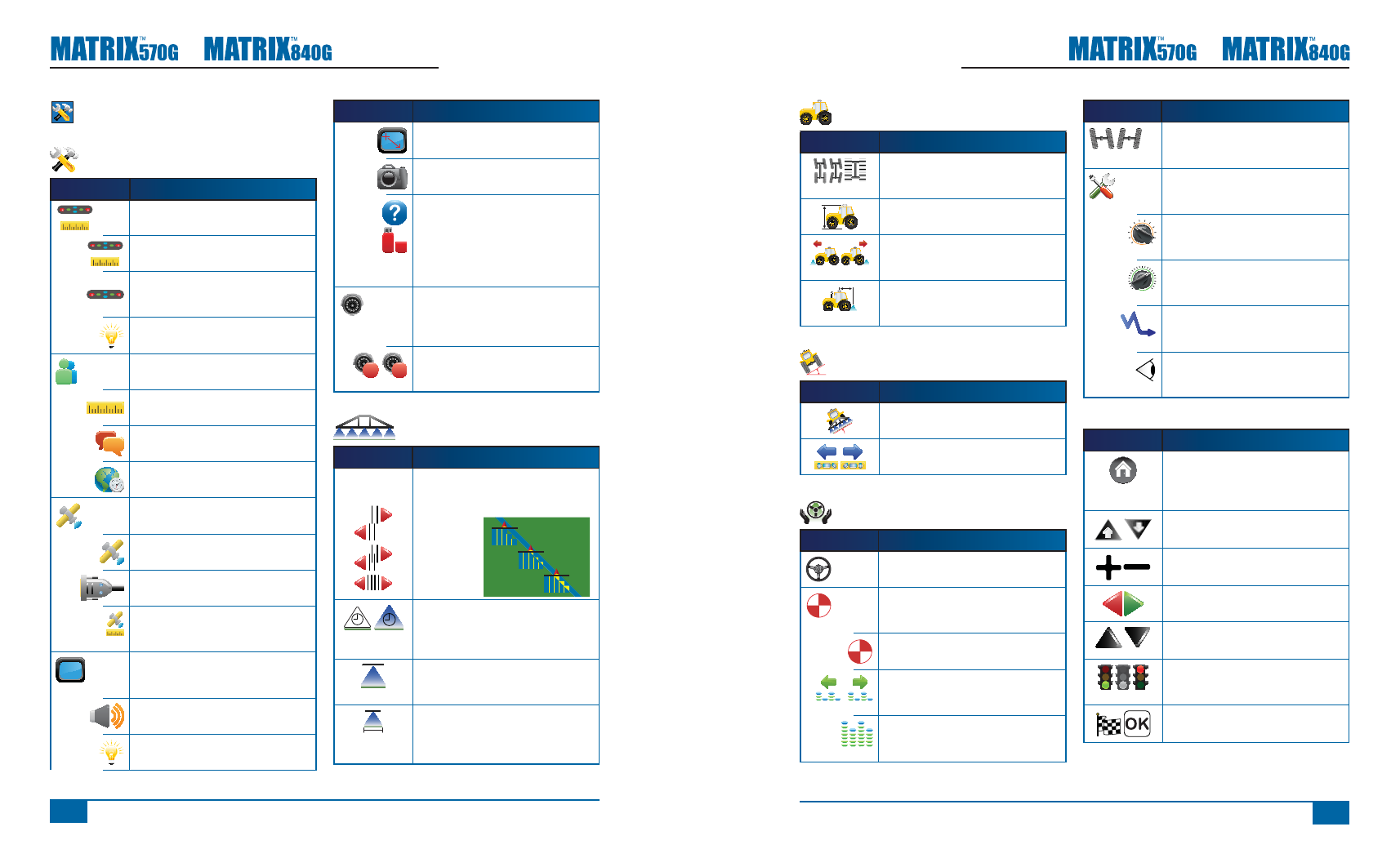
Vehicle Setup
Icon
Description
Vehicle Type. Selects type of vehicle
steering that most closely represents your
vehicle.
Antenna Height. Sets the height of the
GPS antenna from the ground.
Direction to Boom. Sets if the boom is
located behind or in front of the GPS
antenna.
Boom Offset Distance. Defi nes the
horizontal distance from GPS Antenna to
the boom.
Tilt Gyro Module Setup
Icon
Description
Tilt Correction On/Off. Turns tilt correction
on or off.
Level Tilt Positions. Calibrates Tilt
Correction.
FieldPilot Setup
Icon
Description
Autosteer. Sets FieldPilot to on or off.
Valve Setup – Valve Frequency,
Minimum Duty Cycle Left/Right and
Maximum Duty Cycle.
Valve Frequency. Used to drive the steering
valve.
Minimum Duty Cycle. Sets minimum
amount of drive required to begin steering
vehicle left/right.
Maximum Duty Cycle. Sets the maximum
speed that the wheels will steer from left to
right/right to left (lock to lock).
Icon
Description
Valve Test Left/Right. Verifi es steering is
directed properly. Used to fi ne tune oil fl ow
to calibrate wheel timing.
Confi gure FieldPilot – Coarse Steering
Adjustment, Fine Steering Adjustment,
Deadband and Look Ahead.
Coarse Steering Adjustment. Adjusts how
aggressively the vehicle maintains the
guideline in Straight A-B Guidance mode.
Fine Steering Adjustment. Adjusts how
aggressively the vehicle maintains the
guideline in Curved A-B Guidance mode.
Deadband. Adjusts steering if it is too
choppy/responsive or vehicle remains
consistently off the guideline.
Look Ahead. Used during Straight A-B
Guidance mode to adjust the vehicle’s
approach to the guideline.
Commandes générales
Icon
Description
Home Button. Access Home Menu options
including Unit Setup, Vehicle View, Field
View, RealView Guidance, Job View and
Boom Monitoring.
Zoom In/Out Buttons. Adjust zoom settings
in Vehicle View and Field View.
Plus & Minus Icons. Used to increase or
decrease a setting.
Red = Page Left or Start Test Left.
Green = Page Right or Start Test Right.
Up & Down Icons. Used to change a
setting or increase or decrease the setting.
Stop Light. Green Light = Start Testing,
Red Light = Stop Testing,
Grayed = Testing off.
Finish and OK. Both are used to complete
a task.
Unit Setup
System Setup
Icon
Description
Lightbar Setup – LED Spacing, Display
Mode and LED Brightness.
LED Spacing. Sets the distance illustrated
by the illuminated LEDs.
Display Mode. Determines whether the
lightbar represents the swath position or
vehicle position.
LED Brightness. Adjusts brightness of the
lightbar LEDs.
Culture Setup – Units, Language and
Time Zone.
Units. Defi nes the system measurements.
Language. Defi nes the system language.
Time Zone. Establishes the local time
zone.
GPS Setup – GPS Type, GPS Port and
GPS Status Information
GPS Type. Customizes system to accept
GPS, DGPS, or either type of signal.
GPS Port. Sets COM port transmission to
Internal or External.
GPS Status. Displays information
regarding data rates, number of satellites in
view, and satellite quality and ID.
Console Setup – Volume, LCD
Brightness, Touch-screen Calibration,
Screenshot and About/Save.
Volume. Adjusts volume level of audio
speaker.
LCD Brightness. Adjusts brightness of the
console display.
Icon
Description
Touch Screen Calibration. Used to initiate a
touch screen calibration.
Screenshot. Allows screen images to be
saved to a USB drive.
About. Displays information regarding
system software as well as the software
versions of modules connected to the CAN
bus.
Save. Saves console setup data to a USB
drive.
Video Setup. Used to confi gure
up to 8 cameras with the use of a
Video Selection Module. Gray = VSM
unavailable.
A
B
Cameras. Confi gure cameras to normal,
reverse, upside down or reverse upside
down.
BoomPilot/Single Boom Setup
Icon
Description
Overlap. Determines the amount of overlap
allowed when the boom sections are
turned on and off using BoomPilot.
0% Overlap
50% Overlap
100% Overlap
Delay Off/On. Functions as a look ahead
for timing the boom section valves to
switch off or on when entering or exiting an
area that has already been applied.
#
Number of Boom Sections. Sets the
number of boom sections (1 to 15
depending on SmartCable or SDM).
Boom Section Width(s). Designates the
width for the entire swath or individual
boom sections (depending on SmartCable
or SDM availability on the system).