TeeJet Matrix 840G User Manual User Manual
Page 20
www.teejet.com
26
●
98-05141 R2
27
●
External Receiver Minimum Confi guration
Requirements
Before the Matrix will connect and work with an
external GPS receiver, these minimum confi guration
requirements must be met.
Serial Port Settings
Baud rate:
19,200
Data Bits:
8
Parity:
None
Stop Bits:
1
Serial Port connection requirements
Male 9 pin RS-232 serial cable
NOTE: May require Null modem adapter
depending on pin out of receiver.
NMEA Strings
GGA
5 Hz
VTG
5 Hz
ZDA
0.2 Hz
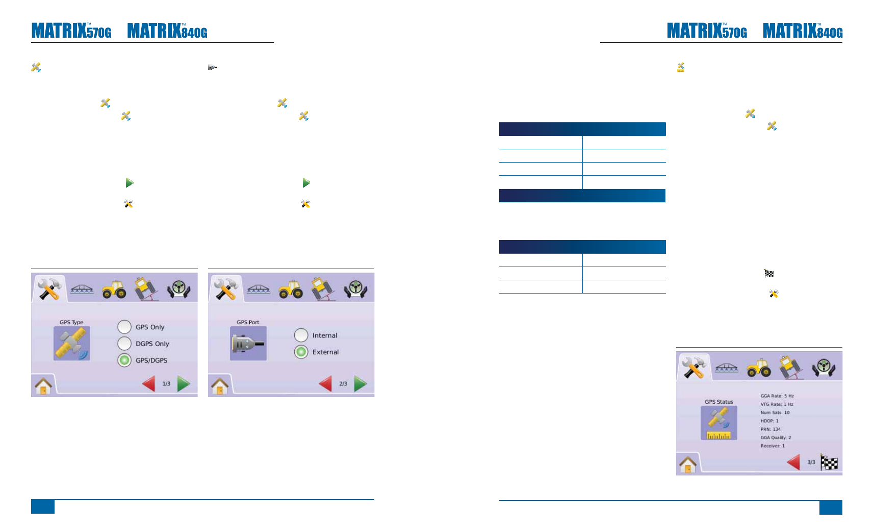
GPS Status
GPS Status displays information regarding data
rates, number of satellites in view, and satellite
quality and ID.
1. Press GPS ICON .
2. Press GPS PORT ICON to view data
including:
◄GGA/VTG (Data Rates) – the number of GPS
positions per second.
◄Num Sats – the number of GPS satellites in
view (minimum of 4 are required for DGPS)
◄HDOP – a measure of satellite geometry
strength in the horizontal plane. A HDOP value
of less than 2 is preferred.
◄PRN – the current DGPS satellite ID. (see
PRN chart)
◄GGA Quality – the current quality indicator of
the GPS signal. (see GGA chart)
3. Press
►CHECKERED FLAG to complete GPS
Setup.
►SYSTEM SETUP TAB to return to main
System Setup screen.
NOTE: If GPS is not available, all entries will be
“Invalid”
Figure 2-18: GPS Status
GPS Type
GPS Type customizes system to accept GPS source
or DGPS source transmissions.
1. Press GPS ICON .
2. Press GPS TYPE ICON .
3. Select
►GPS Only – uncorrected signals
►DGPS Only – differentially corrected signals
►GPS/DGPS – either type of signal
4. Press
►PAGE RIGHT ARROW to proceed to GPS
Port.
►SYSTEM SETUP TAB to return to main
System Setup screen.
NOTE: This setting is required for FieldPilot and
Tilt Sensor Operation, as well as proper
BoomPilot operation.
Figure 2-16: GPS Type
GPS Port
GPS Port sets port transmission to Internal or
External.
1. Press GPS ICON .
2. Press GPS PORT ICON .
3. Select
►Internal – use the internal (D)GPS (if
equipped) and transmit out
►External – receive external (D)GPS data
4. Press
►PAGE RIGHT ARROW to proceed to GPS
Status.
►SYSTEM SETUP TAB to return to main
System Setup screen.
NOTE: This setting is required for FieldPilot and
Tilt Sensor Operation, as well as proper
BoomPilot operation.
Figure 2-17: GPS Port
NOTE: Working with GPS signals such as Omnistar
HP/XP or RTK will require GPS port to be
set to External.