Vehicle setup, Single boom setup – TeeJet Matrix 840G User Manual User Manual
Page 27
www.teejet.com
40
●
98-05141 R2
41
●
VEHICLE SETUP
Vehicle Setup is used to confi gure
Vehicle Type, Antenna Height, Direction
to Boom, and Boom Offset Distance.
1. Select UNIT SETUP from Home Menu
.
2. Press VEHICLE SETUP TAB .
3. Select from:
►Vehicle Type
– selects the type of
vehicle that most closely represents your vehicle
►Antenna Height
– sets the height of the
antenna from the ground
►Direction to Boom
– sets whether the
boom is located behind or in front of the GPS
antenna
►Boom Offset Distance
– defi nes the
distance from the GPS antenna to the boom
OR
Press PAGE RIGHT ARROW to cycle through
all settings.
NOTE: Options labels are current settings. While in
a setting screen, press icon to view available
factory settings and setting ranges.
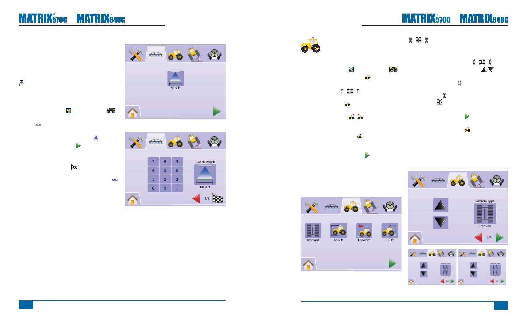
Figure 2-47: Vehicle Setup
Vehicle Type
Vehicle Type selects the type of vehicle steering that
most closely represents your vehicle.
1. Press VEHICLE TYPE ICON
2. Press UP/DOWN ARROW ICONS to
change between:
►Front Wheel Steer
(also used for
Combines)
►Articulated
►Tracked
3. Press
►PAGE RIGHT ARROW to proceed to
Antenna Height.
►VEHICLE SETUP TAB to return to main
Vehicle Setup screen.
NOTE: This setting is required for FieldPilot and
Tilt Sensor Operation, as well as proper
BoomPilot operation.
Figure 2-48: Vehicle Type
Single Boom Setup
Single Boom Setup is available when a SmartCable
or Section Driver Module (SDM) is not present.
Confi gurations for Overlap, Delay On, Delay Off,
Number of Boom Sections will not be available, and
only one boom section width can be entered.
Boom Section Width
Boom Section Width establishes the width of entire
swath. Range is 34.0 - 1968.5 inches / 0.9 - 50.0
meters.
1. Select UNIT SETUP from Home Menu
.
2. Press BOOMPILOT/SINGLE BOOM SETUP
TAB .
3. Press
►BOOM SECTION WIDTH ICON .
►PAGE RIGHT ARROW .
4. Use the entry screen to establish swath width.
5. Press
►CHECKERED FLAG to complete Boom
Section Setup.
►BOOMPILOT/SINGLE BOOM SETUP TAB
to return to main Boom Section Setup screen.
NOTE: Options label is current setting. While in a
setting screen, press icon to view available
factory settings and setting ranges.
NOTE: This setting is required for FieldPilot and Tilt
Sensor Operation.
Figure 2-45: Single Boom Section Width (No SDM)
Figure 2-46: Single Boom Section Width Entry