TeeJet Matrix 840G User Manual User Manual
Page 31
www.teejet.com
48
●
98-05141 R2
49
●
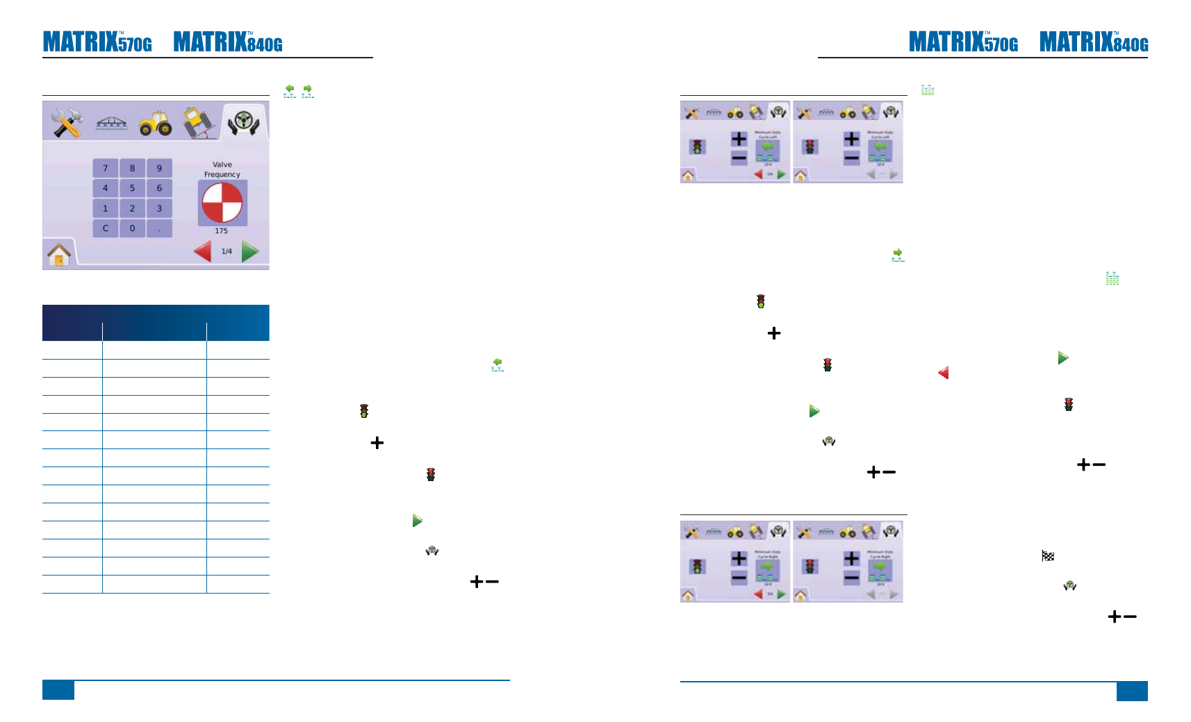
Figure 2-65: Minimum Duty Cycle Left
Cycle Right
Cycle Right sets the minimum amount of drive
required to begin steering the vehicle to the right. .
1. Press MINIMUM DUTY CYCLE RIGHT ICON .
2. While the vehicle is moving in a slow forward
straight line motion, press the GREEN
STOPLIGHT .
3. Slowly increase the duty cycle number using the
PLUS BUTTON until the vehicle begins to
turn right.
4. Press the RED STOPLIGHT to complete the
right test.
5. Press
►PAGE RIGHT ARROW to proceed to
Maximum Duty Cycle.
►FIELDPILOT SETUP TAB to return to
main FieldPilot Setup.
NOTE: Press & hold PLUS/MINUS ICONS to
quickly adjust settings.
Figure 2-66: Minimum Duty Cycle Right
Maximum Duty Cycle
Maximum Duty Cycle sets the maximum speed that
the wheels will steer from left to right / right to left
(lock to lock). Range is 25 - 100.
NOTE: If the valve frequency is below 15 Hz (non
proportional), set the value to 100. Speed
will be established during the Valve Test.
WARNING: PINCH POINT HAZARD!
To prevent serious injury or death, avoid
unsafe practice while manually operating
hydraulic steering circuits. Keep others away
and stay clear of mechanical linkages.
1. Press MAXIMUM DUTY CYCLE ICON .
2. Set Max Duty Cycle value to approximately 60
(or refer to FieldPilot manual for desired lock to
lock times).
3. Turn the wheels all the way to the left (or right).
4. Press the GREEN ARROW (or RED ARROW
). This will start a timer below the STOPLIGHT
as well as turn the vehicle to the right (or left).
5. Press the RED STOPLIGHT when the
wheels are all the way to the right (or left). The
time displayed under the STOPLIGHT is the lock
to lock time.
6. Press the PLUS/MINUS ICONS to adjust
the Max Duty Cycle value.
7. Repeat steps 3 through 6.
8. When the time from left to right / right to left (lock
to lock) begins increasing (it takes longer to turn
the tires) press
►CHECKERED FLAG to complete Valve
Setup.
►FIELDPILOT SETUP TAB to return to
main FieldPilot Setup.
NOTE: Press & hold PLUS/MINUS ICONS to
quickly adjust settings.
Figure 2-64: Valve Frequency
The following are common frequencies/valves:
TeeJet Technologies
Part #
Valve
Frequency
35-02151
FP, CC, NP
2 hz
35-02152
FP, OC, HF, NP
2 hz
35-02153
FP, OC, NP
2 hz
35-02173
FP, PC, LS, NP
2 hz
35-02172
FP, PC, PWM, LS
175 hz
35-02179
FP, PC, PWM, LS
175 hz
35-02180
FP, CC, PWM
110 hz
35-02181
FP, CC, PWM, LS
110 hz
35-02182
FP, CC, PWM
175 hz
35-02183
FP, CC, PWM 1.1 OC 110 hz
35-02184
FP, CC, PWM 7.9 OC 175 hz
35-02185
FP, CC, PWM 2.1 OC 110 hz
35-02186
FP, CC, PWM 4.0 CC 110 hz
35-02187
FP, CC, PWM 7.9 CC 175 hz
For valves manufactured by sources other than
TeeJet Technologies, refer to manufacturer’s
specifi cations for appropriate valve frequency.
Minimum Duty Cycle
Minimum Duty Cycle sets the minimum amount of
drive required to begin steering the vehicle left or
right. Range is 0.0 - 50.0.
RECOMMENDATION – Have a large area of clear
space available to perform test cycles.
NOTE: If the valve frequency is set below 15 Hz
(non proportional), set the amount of drive to
“25.0”. Cycle test is not necessary.
WARNING: PINCH POINT HAZARD!
To prevent serious injury or death, avoid
unsafe practice while manually operating
hydraulic steering circuits. Keep others away
and stay clear of mechanical linkages.
Cycle Left
Cycle Left sets the minimum amount of drive
required to begin steering the vehicle to the left. .
1. Press MINIMUM DUTY CYCLE LEFT ICON .
2. While the vehicle is moving in a slow forward
straight line motion, press the GREEN
STOPLIGHT .
3. Slowly increase the duty cycle number using the
PLUS BUTTON until the vehicle begins to
turn left.
4. Press the RED STOPLIGHT to complete the
left test.
5. Press
►PAGE RIGHT ARROW to proceed to
Minimum Duty Cycle Right.
►FIELDPILOT SETUP TAB to return to
main FieldPilot Setup.
NOTE: Press & hold PLUS/MINUS ICONS to
quickly adjust settings.