Tilt gyro module setup – TeeJet Matrix 840G User Manual User Manual
Page 28
www.teejet.com
42
●
98-05141 R2
43
●
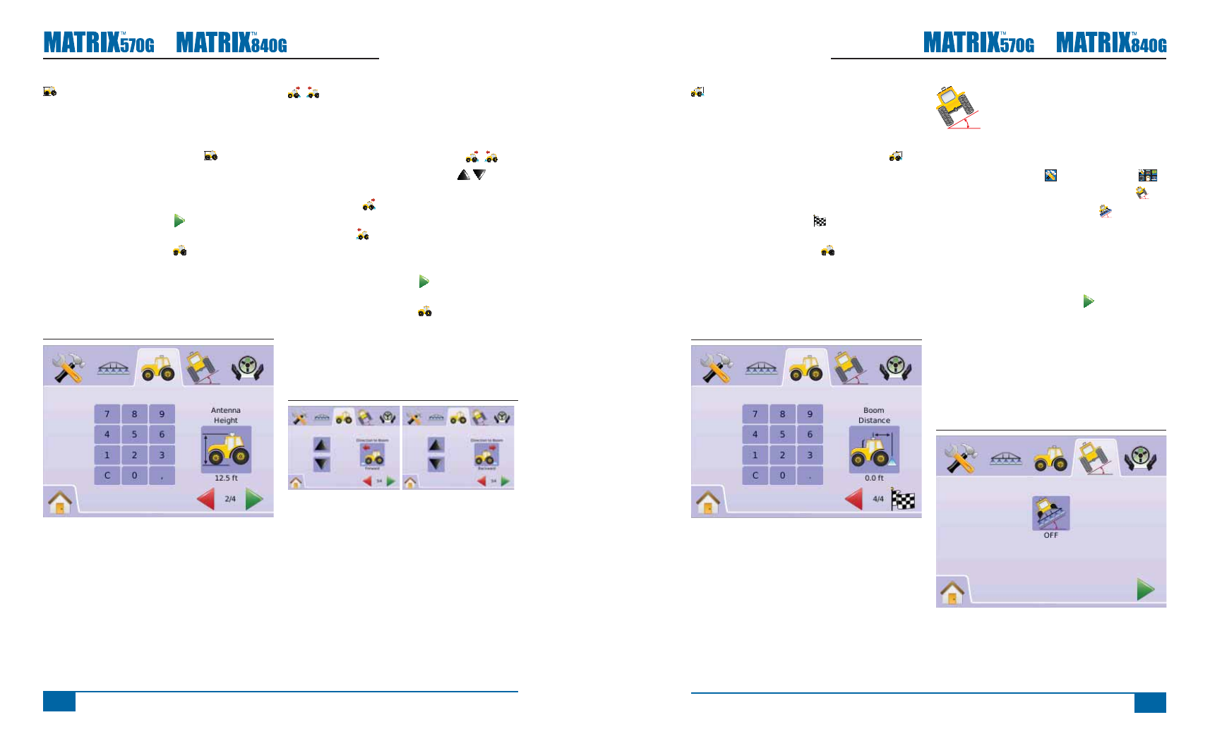
Boom Offset Distance
Boom Offset Distance defi nes the distance from the
GPS antenna to the boom.
Range is 0.0 - 164.0 feet / 0.0 - 50.0 meters.
1. Press BOOM OFFSET DISTANCE ICON
.
2. Use the entry screen to establish the offset
distance.
3. Press
►CHECKERED FLAG to complete Vehicle
Setup.
►VEHICLE SETUP TAB to return to main
Vehicle Setup screen.
NOTE: This setting is required for FieldPilot and
Tilt Sensor Operation, as well as proper
BoomPilot operation.
Figure 2-51: Boom Offset Distance
TILT GYRO MODULE
SETUP
The Tilt Gyro Module (TGM) is used
to calibrate the gyro, allowing for tilt correction for
application on hilly or sloped terrain.
1. Select UNIT SETUP from Home Menu
.
2. Press TILT GYRO MODULE SETUP TAB
3. Press TILT CORRECTION ICON
4. Select
►On – tilt correction will be applied to the GPS
antenna position
►Off – tilt correction will not be applied
OR
Press PAGE RIGHT ARROW to cycle through
all settings.
NOTE: If FieldPilot is being used, a Tilt Gyro Module
is built into the system.
NOTE: Antenna Height must be entered prior to Tilt
Calibration.
NOTE: Option label is current setting.
Figure 2-52: Tilt Correction
Antenna Height
Antenna Height sets the height of the antenna from
the ground. Range is 0.0 - 32.8 feet / 0.0 - 10.0
meters.
1. Press ANTENNA HEIGHT ICON
.
2. Use the entry screen to establish the antenna
height.
3. Press
►PAGE RIGHT ARROW to proceed to
Direction to Boom.
►VEHICLE SETUP TAB to return to main
Vehicle Setup screen.
NOTE: This setting is required for FieldPilot and
Tilt Sensor Operation, as well as proper
BoomPilot operation.
Figure 2-49: Antenna Height
Direction to Boom
Direction to Boom sets whether the boom is located
behind or in front of the GPS antenna as the vehicle
moves in a forward direction.
1. Press DIRECTION TO BOOM ICON
2. Press UP/DOWN ARROW ICONS to
change between:
►Backward
– indicates the boom is located
behind the GPS antenna
►Forward
– indicates the boom is located
in front of the GPS antenna
3. Press
►PAGE RIGHT ARROW to proceed to Boom
Offset Distance.
►VEHICLE SETUP TAB to return to main
Vehicle Setup screen.
NOTE: This setting is required for FieldPilot and
Tilt Sensor Operation, as well as proper
BoomPilot operation.
Figure 2-50: Direction to Boom