Configurations, Speed out / sense in cable, Matrix fieldpilot boompilot optional accessory – TeeJet Matrix 840G User Manual User Manual
Page 11
www.teejet.com
8
●
98-05141 R2
9
●
CONFIGURATIONS
The following diagrams are refl ective of typical Matrix confi gurations. Due to the variety of possible
confi gurations, these should be used for reference purposes only.
Figure 1-14: Matrix w/RealView Camera
16-00022: Camera
Co
n
n
e
c
t
to
+1
2
v
O
n
ly
Powe
r
C
able
45-05645
Power
Cable, 12V
45-05775
10' Power
Cable, Battery
CAUTION CONN.
TO +12V ONLY
PO
W
E
R CABLE
45-
05775
DC: X
X
X
X
8 Pos.
4 Pos.
8 Pos.
Speed Cable
Camera
45-05617: 20'
45-05618: 60'
Camera Extension Cable
45-05615 4 Pos.
45-05765 8 Pos.
Speed/Sense Cable
5 Pos.
+12V
32-50008
Switch
78-50155
GPS Ant.
Matrix 570G
75-30055
75-30056 w/ClearPath
Kit, RAM Mount w/Suction Cup
90-02349 (Matrix 570G)
90-02700 (Matrix 840G)
Matrix 840G
75-30070
75-30071 w/ClearPath
Matrix
FieldPilot
BoomPilot
Optional Accessory
Speed Out / Sense In Cable
The Speed Out / Sense In Cable assists the Matrix with two additional connections that::
►Send a radar speed signal to an external device
►Allow the user to operate the area applied function of the Matrix in series with a remote master connection
or existing apply on/off toggle in a single swath manner. However if the previous connections are not
available the supplied toggle switch allows area applied functionality without the need to connect to a
functional application implement.
Connecting to different consoles requires different adapters and calibrations.
• If connecting to TeeJet consoles use speed adapter 45-20042
◄enter calibration # 914 (#1000 in Europe) for 8xx series in RAD mode,
◄enter calibration # 9140 (#10000 in Europe) for below LH 70 Series, LH 85, 500 series, 5000, 6000,
IC 24 and IC 34
• If connecting to Mid-Tech consoles no adapter is required,
◄enter calibration # 1000
• If connecting to Raven consoles use speed adapter 45-05508 (do not connect the 12v red wire from
45-05508)
◄enter calibration # 730 in SP 2
If sensing boom shut-off for applied mapping from an existing console, attach the green wire to the valve side
of the master switch on the console. The red wire is not used.
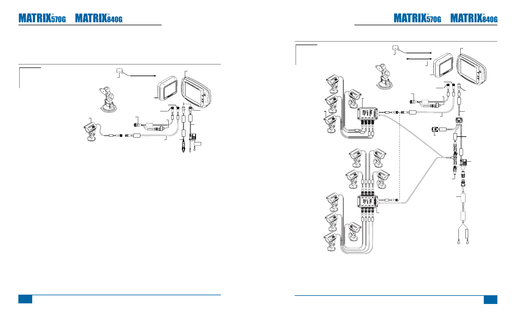
Figure 1-15: Matrix w/8 Channel or 4 Channel VSM & Multiple RealView Cameras
PO
W
E
R
I
N
CAN
RS-232
Po
w
e
r/
D
A
T
A
45-
0
56
26
45-05626
Pwr/CAN/Data
Cable
(included with
FieldPilot and
BoomPilot kits)
3A Fuse
8 Pos.
RS-232
TJ CAN
(Terminated)
CA
UT
IO
N:
CO
NNE
C
T
TO
1
2
V
O
N
L
Y
Pow
e
r Cab
le
401
-00
16
DC: xx
/xx
W
A
RNI
N
G CO
NNE
C
T
DIRE
CT
L
Y
T
O
B
A
T
.
401-0016
Battery Adapter
45-08101
CAN Terminator
16-00022
RealView Camera
78-08067
Module, 4CH
Video CAN
78-08068
Video Selector
Module,
8CH Video CAN
to Optional RXA GPS Antenna
45-05678
Cable, SMA-M X SMA-M
4 Pos.
8 Pos.
Speed Cable
Camera
45-05617: 20'
45-05618: 60'
Camera Extension Cable
45-05615 4 Pos.
45-05765 8 Pos.
Speed/Sense Cable
5 Pos.
+12V
32-50008
Switch
78-50155
GPS Ant.
Matrix 570G
75-30055
75-30056 w/ClearPath
Kit, RAM Mount w/Suction Cup
90-02349 (Matrix 570G)
90-02700 (Matrix 840G)
Matrix 840G
75-30070
75-30071 w/ClearPath
Matrix
FieldPilot
BoomPilot
Optional Accessory