2 storage and installation checks, Reznor, Receiving, moving, and storage (cont'd) – Reznor MAPS II Unit Installation Manual User Manual
Page 6: 1 receiving and moving (cont'd)
Form I-MAPS II, Page 6
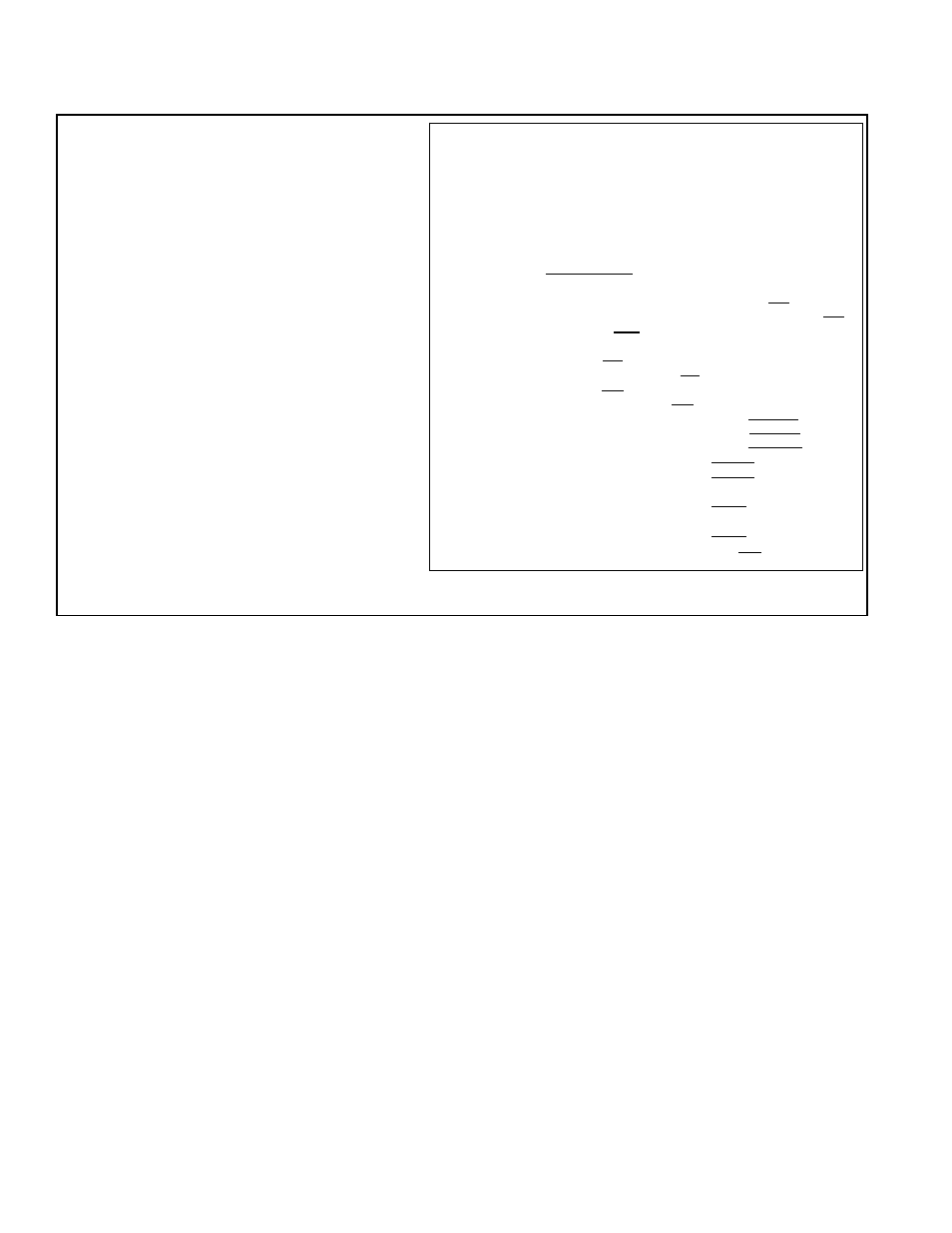
Gas Heat Section Rating Plate Key:
A = ANSI Standard Date
B = CSA Standard Date
C = Model No.
D = Amps
E = Type of Gas (natural or propane)
F = Orifice Size of Large Burner
G = Orifice Size of Small Burner
H = Normal BTUH Input (sea level)
I = Thermal Output BTUH (sea level)
J = Minimum BTUH Input (sea level)
K = Manifold Pressure
L = Minimum Gas Supply Pressure
M = Maximum Throughput
N = Minimum Throughput
P = Manufacturing Date (Month/Year)
Q = Altitude in Feet
R = Altitude in Meters
FIGURE 1B - Sample of a Gas-Fired
Heat Section Rating Plate (applies to
Models RDCA and RDDA)
3.2 Storage and
Installation
Checks
If this system is going to be stored, take precautions to prevent condensate
formation inside the electrical compartments and motors. To prevent damage
to the unit, do not store sitting on the ground.
After the system has been moved to its installation site, remove all of the ship-
ping brackets and check all of the fans for free movement. See the check
lists in Paragraph 10 before starting the unit and complete the Startup Form
(shipped in the literature envelope).
DUCT FURNACE/GÉNÉRATEUR D'AIR CHAUD À GAINE
CATEGORY III/CATÉGORIE III
FOR INDUSTRIAL/COMMERCIAL USE ONLY
POUR USAGE INDUSTRIEL/COMMERCIAL
ANSI Z83.8b - [ A ]
CGA 2.6b-M [ B ] DUCT FURNACE/GÉNÉRATEUR D'AIR CHAUD À GAINE
MODEL/MODÈLE [ C
] [ P ]
SERIAL NO./#DE SÉRIE:
[ ]
230 VOLTS 1 PH 60 HZ MAXIMUM TOTAL INPUT [ D ] AMPS
CONSOMMATION TOTALE MAX. DE [ D ] A
TYPE OF GAS/TYPE DE GAZ: [ E ]
ALTITUDE [ Q ] FEET/PIEDS, [ R ] MÈTRES
LARGE BURNER ORIFICE SIZE [ F ] DRILL HAS BEEN FACTORY ADJUSTED
GRAND BRULEUR DIMENSION DE L'ORIFICE [ F ] FORET
SMALL BURNER ORIFICE SIZE [ G ] DRILL HAS BEEN FACTORY ADJUSTED
PETIT BRULEUR DIMENSION DE L'ORIFICE [ G ] FORET
NORMAL INPUT/ENTRÉE NORMALE
[
H ] BTU/HR
THERMAL OUTPUT CAPACITY/RENDEMENT THERMIQUE [ I ] BTU/HR
MINIMUM INPUT/ENTRÉE MIN.
[ J ] BTU/HR
NORMAL MANIFOLD PRESSURE
[ K
] IN.W.C.
PRESSION NORMALE DE LA TUB
[ K
] PO/COL D'EAU
MIN. PERMISSIBLE GAS SUPPLY PRESSURE
FOR PURPOSE OF INPUT ADJUSTMENT.
[ L ] IN.W.C.
PRES. D'ALIM. MIN. ACCEPTABLE DE GAZ POUR
DES FIN DE RÉGLAGE DE L'ENTRÉE
[
L ] PO/COL D'EAU
MAXIMUM THROUGHPUT / MINIMUM THROUGHPUT [
M ] / [ N ] C.F.M.
CONSOMMATION MAXIMUM / MINIMUM [ M ] / [ N ] PI3/MN
REZNOR
MERCER, PA USA 16137
Check for shipped-separate accessories and shipped-loose parts.
All heating systems and cooling only systems with Option DU1 have a dis-
charge sensor temporarily installed in the control compartment for the conve-
nience of the installer at startup. (NOTE: Cooling only systems without Option
DU1 have a discharge air sensor installed in a permanent location.) Depending
on the application and optional controls, a sensor installed in a temporary loca-
tion will have to either be relocated to the ductwork.
The roof curb is shipped separately (See Paragraph 5.2), and in most cases, in
advance of the unit. A Model JHUP-0250 duct furnace curb section, an outside
air hood, hood for optional power exhaust, optional economizer, or optional
energy recovery module are shipped separately for field installation.
If ordered as options or components of options, other items that are shipped
separately include a remote console, a disconnect switch, a discharge temper-
ature control, a space temperature control, a space reheat override, an over-
ride thermostat, a room humidistat, a duct smoke detector, and/or a firestat.
Shipped-Separate
Accessories and
Shipped-Loose Parts
3. Receiving, Moving, and Storage (cont'd)
3.1 Receiving and Moving (cont'd)
NOTE: Same type of rating plate applies to a Model JHUP-0250 Curb Duct Furnace.