5 blower motor, 6 condenser fan motors and fans, 7 compressors – Reznor MAPS II Unit Installation Manual User Manual
Page 26: Electrical and wiring (cont'd)
Form I-MAPS II, Page 26
7.5 Blower Motor
Check the unit rating plate or motor name plate to verify voltage, HP, and type.
Use an amp meter to check motor amps. Amps may be adjusted downward by
reducing blower RPM or increasing duct system static pressure.
Blower motors over 3HP and all motors on systems using 575V include a
starter. 1/2-3HP, 208, 230, and 460 volt motors have internal overload protec-
tion but may be equipped with an optional starter (Option AN10); check the
wiring diagram.
7.6 Condenser Fan
Motors and Fans
All systems have one, two, or three direct-drive, statically and dynamically bal-
anced, permanently lubricated, condenser fan motors. Condenser fan motors
are open dripproof motors with external sling protection against water penetra-
tion and have auto reset thermal overload protection.
Maintain minimum clearances around the fans as illustrated in
FIGURE 3 on
page 9. Above the fans should always be unrestricted, open area.
7. Electrical and
Wiring (cont'd)
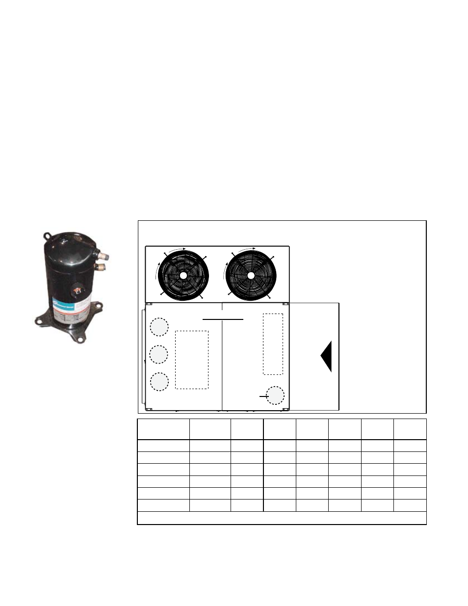
FIGURE 14A -
Compressor
��������
���
�����
��������
���������������
�����������
������
�����������
�������������������������
�
�
�
����
��
�������
FIGURE 14B - Top View
Showing Approximate
Location of Compressors
inside the Cabinet
Compressor Staging
Each Model system leaves the factory with the compressor staging sequence
shown in the table. Models RDCA and RECA have the same staging as Model
RCA. Models RDDA and REDA have the same staging as Model RDA.
(For additional
information,
see Operation/
Maintenance/Service
Manual, Form O-
MAPS II.)
Compressor
Model
ARI
Tonnage
RLA
230 V
LRA
230 V
RLA
460 V
LRA
460 V
RLA
575 V
LRA
575 V
ZR22K3
2
7.9
45
3.9
22.4
N/A
N/A
ZR36K3
3
11.4
77
5.7
39
4.7
31
ZR54KC
4.5
16.4
124
8.2
59.6
6.6
49.4
ZR72KC
6.2
20.7
156
10
70
8.2
54
ZR144KC
12
47.1
245
19.6
125
15.8
100
ZR125KC
10
42
239
19.2
125
13.8
80
Note: Model ZRT144KC uses two ZR72KC compressors in tandum (6.2t).
Compressor Amps/
Voltage
Access
compressors
A,
B, and C through
compressor
section door.
Access
D or Dh
through the filter
section door.
See
FIGURE 20
or 21, page 33.
7.7 Compressors
All of the compressors are high efficiency hermetic scroll type. Circuit A, B, and
C cooling compressors are in the Compressor Section (see
FIGURE 2A or 2B,
page 7 or 8). Circuit D or Dh compressor (D for cooling or Dh for re-heat heat
pump) is located in the cabinet filter section.