Mounting (cont'd), 2 roof curb (cont'd) – Reznor MAPS II Unit Installation Manual User Manual
Page 14
Form I-MAPS II, Page 14
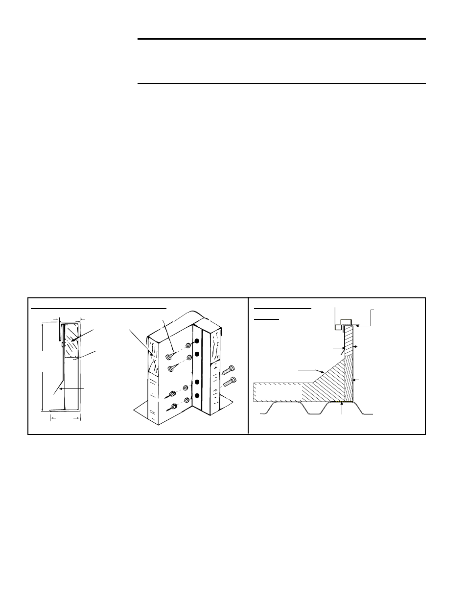
FIGURE 6 - Option
CJ31 Downflow Roof
Curb Cross Section
and Corner Detail
1. Position the roof curb end assemblies and side assemblies as shown in the
drawing in
FIGURE 4, page 12. Fasten with bolts and lag screws as illus-
trated in the corner detail (
FIGURE 6, below).
2. Attach duct sides and ends to create the internal ductwork. Use the sheet-
metal screws to attach the ductwork pieces. (Refer to
FIGURE 4). Attach
the return air duct angles to the attached end and side and to the roof curb.
NOTE: If the system does not have a return air opening, the return air duc-
twork may be installed in the curb but is not required.
3. Check the roof curb for squareness. The curb must be adjusted so that the
diagonal measurements are equal within a tolerance of ± 1/8" (3mm).
4. Level the roof curb. To ensure a good weatherproof seal between the cabi-
net curb cap and the roof curb, the curb must be leveled in both directions
with no twist end to end. Shim as required and secure curb to the roof deck
before installing flashing (See Curb Detail in
FIGURE 6).
5. Install field-supplied flashing.
6. Before placing the unit on the curb, apply 1/4" x 1-1/4" foam sealant tape to
both the top surface of the curb rails and the top surface of the perimeter of
the duct opening(s), being sure to make good butt joints at all corners.
The sealant tape must be applied to the curb rails to prevent water leakage
into the curb area due to blown rain and capillary action.
Downflow Roof Curb Assembly and Installation Instructions
���
��������
������������
��
�������
����������
������
������������
����������
��������������
�������������������
�����������������
��������
���������
���
������
Curb Section and Corner Detail
5.2.2 Curbs for
Horizontal Airflow
(Option CJ50 and
Option CJ49)
Option CJ50 is a 32" (813mm) high curb designed to provide horizontal airflow
into the side of a building or at a location through the roof that is not directly
under the unit. Option CJ49 is the same design but is 36" (914mm) high. Both
curbs are NRCA approved and are constructed of 14 gauge steel with a 2x4
full perimeter wood nailer strip.
Option CJ49 and CJ50 curbs are shipped in sections and require field assem-
bly. Position the curb so that the air inlet of the unit will not be facing into the
prevailing wind. Always comply with the clearances in Paragraph 4.3. Verify
that the curb is the correct size and follow the assembly and installation instruc-
tions shipped with the curb.
For condensate drainage and proper operation, it is important that the instal-
lation be level. To ensure a good weatherproof seal between the unit curb cap
and the curb, the curb must be leveled in both directions with no twist end to
CAUTION: Before installation, recheck to be sure that the cor-
rect curb has been ordered. Be sure that the curb selected
matches the unit ordered. Verify the dimensions of the curb
received with the dimension table in FIGURE 5.
5.2.1 Downflow Roof
Curb, Option CJ31
(cont'd)
5. Mounting (cont'd)
5.2 Roof Curb
(cont'd)
�����������������������������
������������������
����������
�����
����
������
�������
������
�������
������������
�����������
�������
����������������
��������������
����������
��������������
�������������
�����������
Typical Curb
Detail