Mounting (cont'd), 2 roof curb (cont'd) – Reznor MAPS II Unit Installation Manual User Manual
Page 16
Form I-MAPS II, Page 16
������������
�����������
�����������
������������
�������
���������������������
�����������
���������
���������
��������
�����������
����������������
������
������
���������
������
������
���������
��������
������
��������
�����
���������������������
Assembly and Installation Instructions for Option CJ49 and CJ50,
Curbs for Horizontal Airflow
CAUTION: Before installing, recheck to be sure that the cor-
rect curb has been ordered and received. Be sure that the
curb selected matches the unit ordered. Verify the dimen-
sions of the curb received with the dimension table in FIG-
URE 7A.
Verify all the components and be sure that the curb is correct for the system
being installed. A short version of the installation instructions is included in this
manual. When assembling, follow the complete step-by-step illustrated instruc-
tions included with the curb.
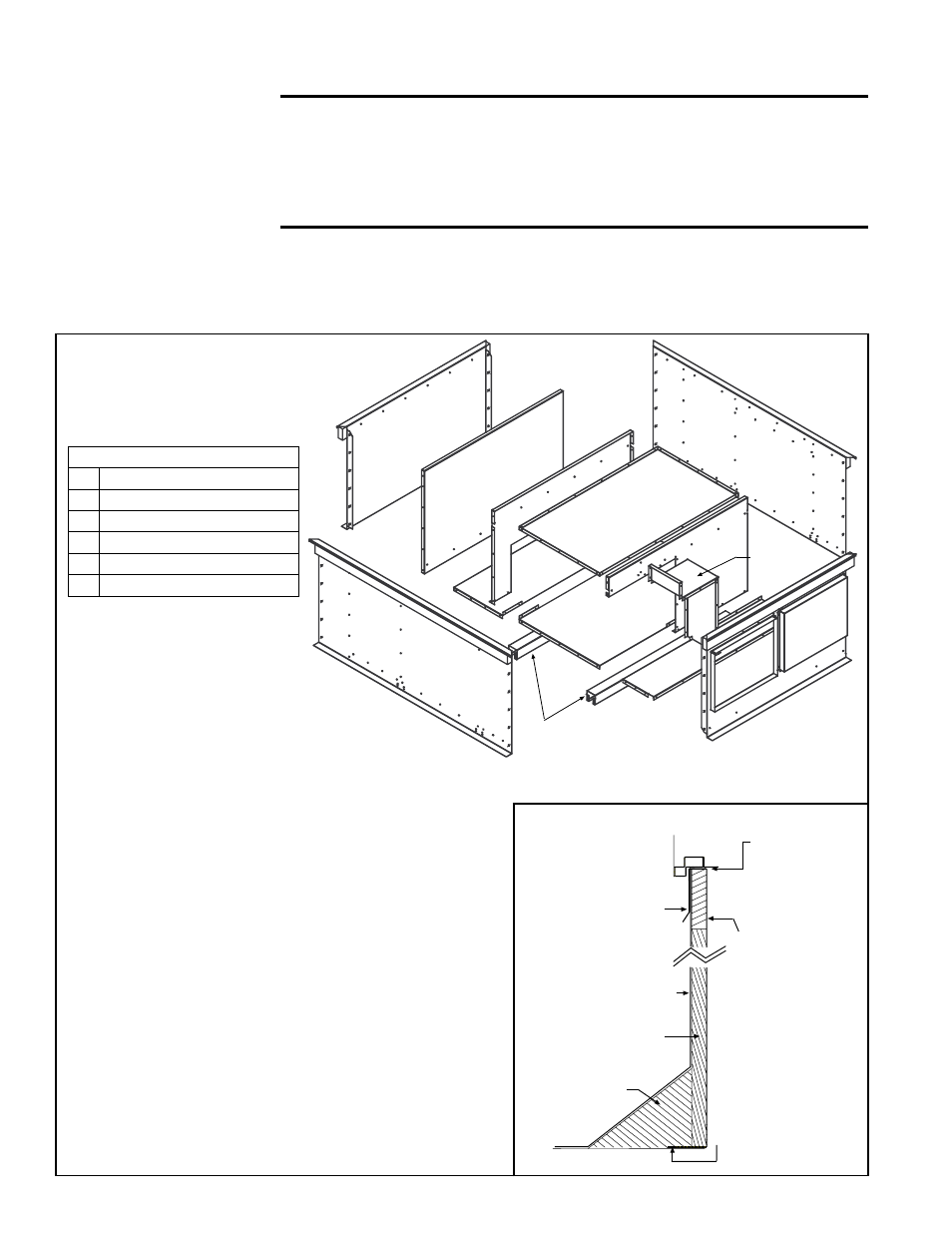
FIGURE 7B - Exploded
View of Horizontal Airflow
Curb Assembly Showing
all Components
Instructions
Layout the four curb sides.
Join the corners using six of the
bolts and washer sets at each corner.
Be sure curb assembly is square.
Line up the holes and use the screws in the
hardware kit to attach the component parts in
the following order:
1 - Two bottom support braces
2 - Divider panel
3 - 3 Bottom panels (supply bottom 1 and 2 and
return bottom)
4 - Supply duct divider
5 - Return divider - 1
6 - Supply duct top panel
7 - Return divider - 2
8 - Return air cover (Install only if the application
does not require return air. If the application
includes return air, this cover is not used.)
Complete curb installation with the following field sup-
plied items: counter flashing, roofing felt, rigid insulation,
and cant strip. See
FIGURE 7C.
Before placing the unit on the curb, apply the 3/4" x
1-1/4" gasket to both the top surface of the curb rails and
the top surface of the perimeter of the duct opening(s),
being sure to make good butt joints at all corners.
������������������
�������������
���������������
����������������
��������������
�����
����
������
�������
������
�����������
������������
����������
�������
�������
��������
��������������
����������
��������������
������������
��������������
FIGURE 7C -
Curb Detail
Hardware Package
Qty Description
24 1/4-20 x 1/2 Hex Bolts with Nuts
24 1/4 Split Lock Washers
24 1/4 Flat Washers
88 10-16 x 1/2 Hex Screws
1 3/4" x 1-1/4" x 14' Gasket
5.2.2 Curbs for
Horizontal Airflow
(Option CJ50 and
Option CJ49) (cont'd)
5. Mounting (cont'd)
5.2 Roof Curb
(cont'd)